EasyManuals Logo

HIKVISION DS-TME401-TPC User Manual

HIKVISION DS-TME401-TPC
24 pages
To Next Page IconTo Next Page
To Previous Page IconTo Previous Page
Page #13 background imageLoading...
Page #13 background image
Entrance/Exit Station Quick Start Guide
12
5 Series Barrier Gate
Switch
LED Display
12 VDC Power Adapter
Entrance/Exit Station
Stop
C ommon
T erm in al
G
N
D
D4
-
D4
+
Barrier Gate
External LED Displ ay
Reserved RS-485
Alarm Output Alarm Input
Wiegand
Vehicle Detector
G
N
D
D3
-
D3
+
D
C
1
2
V
Fall Rise
G
N
D
N
O
1
C
1
G
N
D
A
I
1
D
C
1
2
V
W0
+
W0
-
W1
+
W1
-
G
N
D
G
N
D
D
C
1
2
V
A B G
F
+
F
-
Capture Unit
AUDIO IN
LAN
Control Terminal
P1
P2 P3
P4
LAN
LAN
Live
Line
Zero
Line
220 VA C
Live
Line
Zero
Line
F al lin g
Lim it
R ising
Lim it
G
N
D
Stati on I nte rnal Veh icle Detecto r
Lock
Rise
Stop
Fall
Unl ock
Risi ng
Control +
Risi ng
Control -
Stopping
Control +
Stopping
Control -
Fall ing
Control +
Fall ing
Control -
Fall ing Limit
Output
Risi ng Limit
Output
Risi ng Limit
Detection
Fall ing Limit
Detection
IR/Induction +
IR/Induction -
Protection +
Protection -
GND
RS-485B
RS-485A
VCC
R-LED
G-LED
12 V-IN
GND
12 V-OUT
12 V-OUT
LED-ARR2
LED-ARR1
VDD
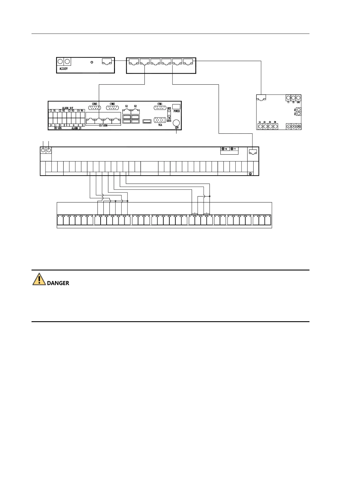
Figure 2-4 Peripheral Devices Wiring
2.3.2 Connect to Power Supply
Cut off power before wiring to avoid accident.
The power voltage of barrier gate is 220 VAC ± 10%. If the voltage exceeds the range, voltage
stabilizer is needed.
Step 1 Connect the laid power cord (RVV3 × 1.5 mm² or above) to the power input of the station.

Questions and Answers:

Question and Answer IconNeed help?

Do you have a question about the HIKVISION DS-TME401-TPC and is the answer not in the manual?

HIKVISION DS-TME401-TPC Specifications

General IconGeneral
BrandHIKVISION
ModelDS-TME401-TPC
CategoryIP Access Controllers
LanguageEnglish

Related product manuals