EasyManuals Logo

HIKVISION ERI-Q104-P4 User Manual

HIKVISION ERI-Q104-P4
13 pages
To Next Page IconTo Next Page
To Previous Page IconTo Previous Page
Page #3 background imageLoading...
Page #3 background image
R E A R P A N E L S
ERI-Q104-P4
LAN&USBVGA
3 4 5 6
48V
2
1
9
ERI-Q104-P8
No. Item Description
1
LAN
Connector for network
2 Power Supply
Input: 100 to 240 VAC
Output to
NVR
: 48 VDC
3
VGA
DB
-
15 connector for VGA output. Displays local video output and menu.
4
HDMI
HDMI video output connector
5
USB Inte
rface
Universal Serial Bus (USB) port for additional devices
6
PoE/IP Camera
Inputs
PoE out and IP camera inputs
7
---
---
8
AUDIO IN/OUT
RCA connectors
9
Ground
Grounding screw
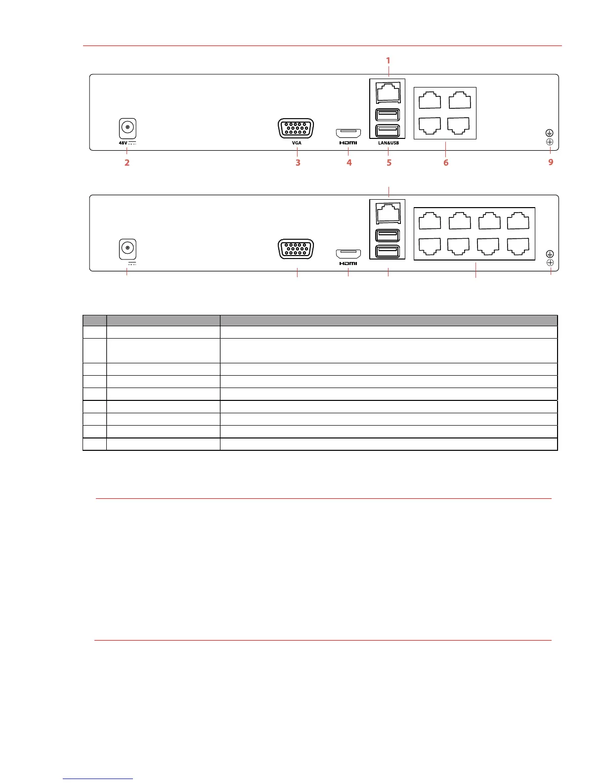
1 C O N N E C T I N G D E V I C E S
Connect power supply to NVR and plug into 110 to 240 VAC outlet (surge suppressor recommended).
Connect NVR to LAN using Cat 5e cable.
Connect video monitor(s) to NVR using HDMI and/or VGA cables, as appropriate.
Connect mouse to USB port (wireless mouse can be used in lieu of included mouse).
Connect to audio I/O using RCA connectors.
Turn power switch on. Power indicator LED will remain on to indicate unit is starting/on.
2S T A R T U P
Proper startup is crucial to expanding the life of the NVR.
Check the power supply is plugged into an electrical outlet.
It is HIGHLY recommended that an Uninterruptible Power Supply (UPS) be used in conjunction with the
device.
The Power LED should turn green. The unit will start.

Questions and Answers:

Question and Answer IconNeed help?

Do you have a question about the HIKVISION ERI-Q104-P4 and is the answer not in the manual?

HIKVISION ERI-Q104-P4 Specifications

General IconGeneral
BrandHIKVISION
ModelERI-Q104-P4
CategoryDVR
LanguageEnglish

Related product manuals