KB88113 Vandal-Resistant Video Intercom Doorbell User Manual
UM KB8113 Doorbell 021821NA 31
Select I/O Input No., Input Mode, Output No., and Output Mode.
Click Save to enable the settings.
For door station, there are four I/O input terminals. By default, Terminals 1 and 2
correspond to Door Status. Terminals 3 and 4 correspond to door switch
interfaces.
For door station, there are two I/O Output Terminals. Terminals 1 and 2
correspond to door station door interfaces (NO1/COM/NC1; NO2/COM/NC2). Door
1 is enabled by default. You can enable/disable IO Out according to needs.
7.4.8 Access Control
Settings
Door Parameters
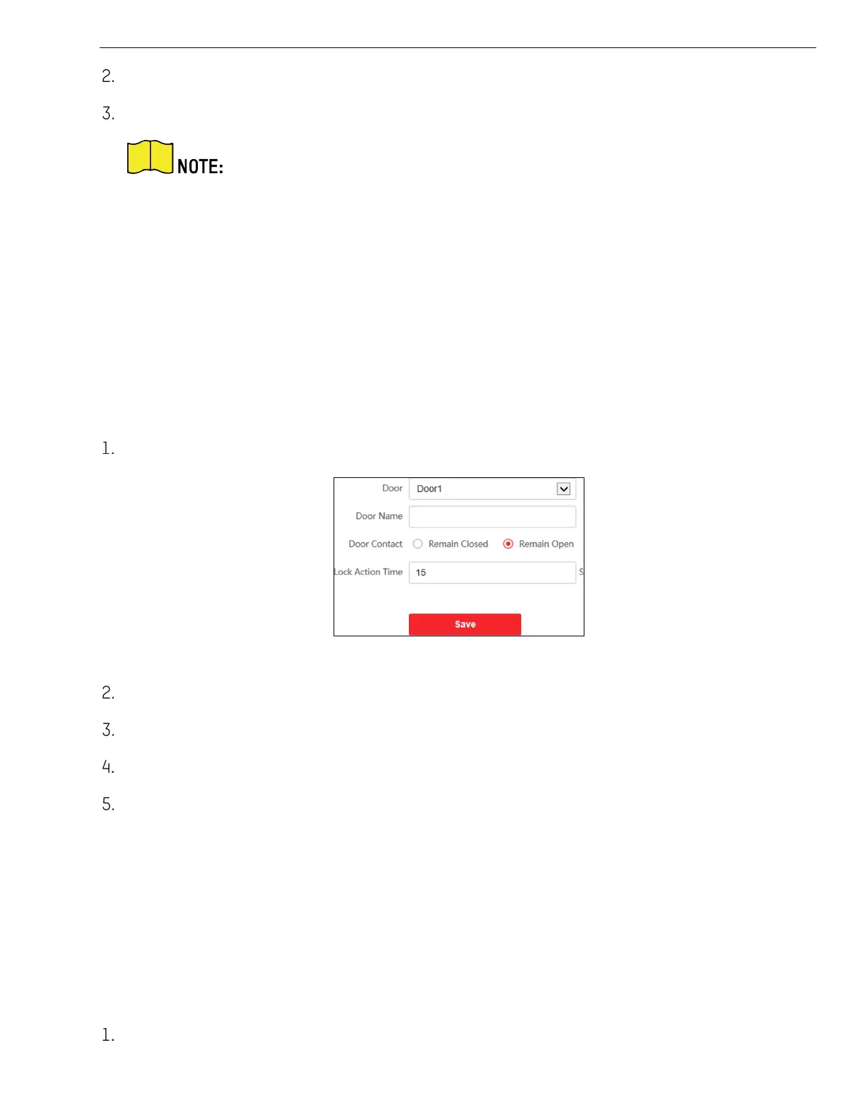
Click Access Control → Door Parameters to enter the settings page.
Figure 7-17 Door Parameters
Select the door and edit the door name.
Set door contact status.
Set lock action time.
Click Save to enable the settings.
Elevator Control
Before You Start
• Make sure your door station is in the mode of main door station. Only the main door station
support elevator control function.
• Make sure your door station has been connected to the elevator controller via RS-485 cable if
you want to use RS-485 interface.
Click Access Control → Elevator Control to enter the corresponding configuration page.