9
ASSEMBLY INSTRUCTIONS
7
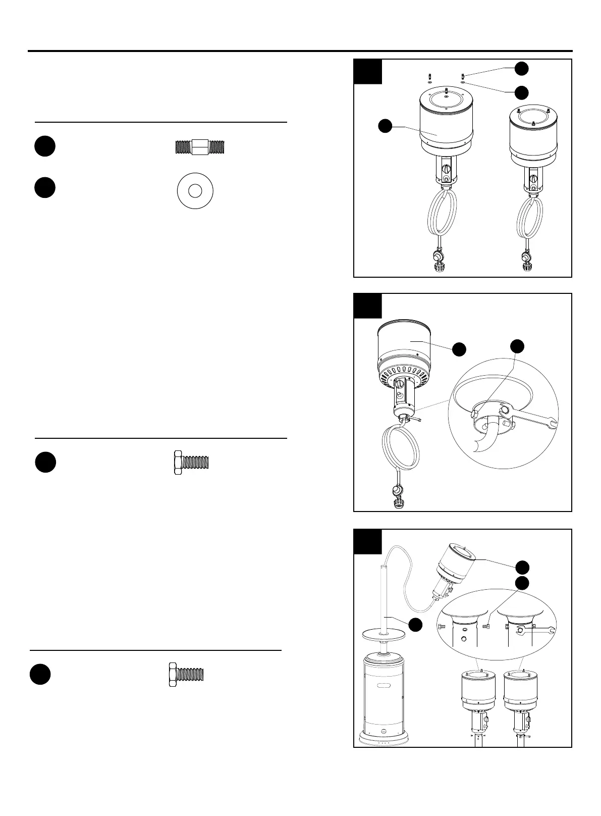
7. Attach reflector spacers (FF) and Ø8 washers
(GG) to the top of head assembly (C). Tighten the
reflector spacers (FF).
C
C
J
LL
C
FF
GG
LL
FF
GG
x 3
Reflector Spacer
x 3
Φ8 Washer
Hardware Used
Hardware Used
LL
8
x 4
Stainless Steel Bolt
8. Unscrew stainless steel bolts (LL) from head
assembly (C).
9
Hardware Used
LL
x 4
Stainless Steel Bolt
9. Insert hose of head assembly (C) into post (J). Secure
head assembly (C) to post (J) with stainless steel
bolts (LL).
Note: The control knob on head assembly (C) should
be above the decal on post (J).
 Loading...