(APPENDIX III) SYNCHRONIZATION| PAGE 48
Said load transfer process is limited in duration (Synchronization parameter table
6). In order to carry out the load transfer process, it is necessary to install
transformers for measuring intensity both at the genset output line (measured by
the CEM7 genset control unit) and the network output line (measured by the
CEC7 transfer switch controller).
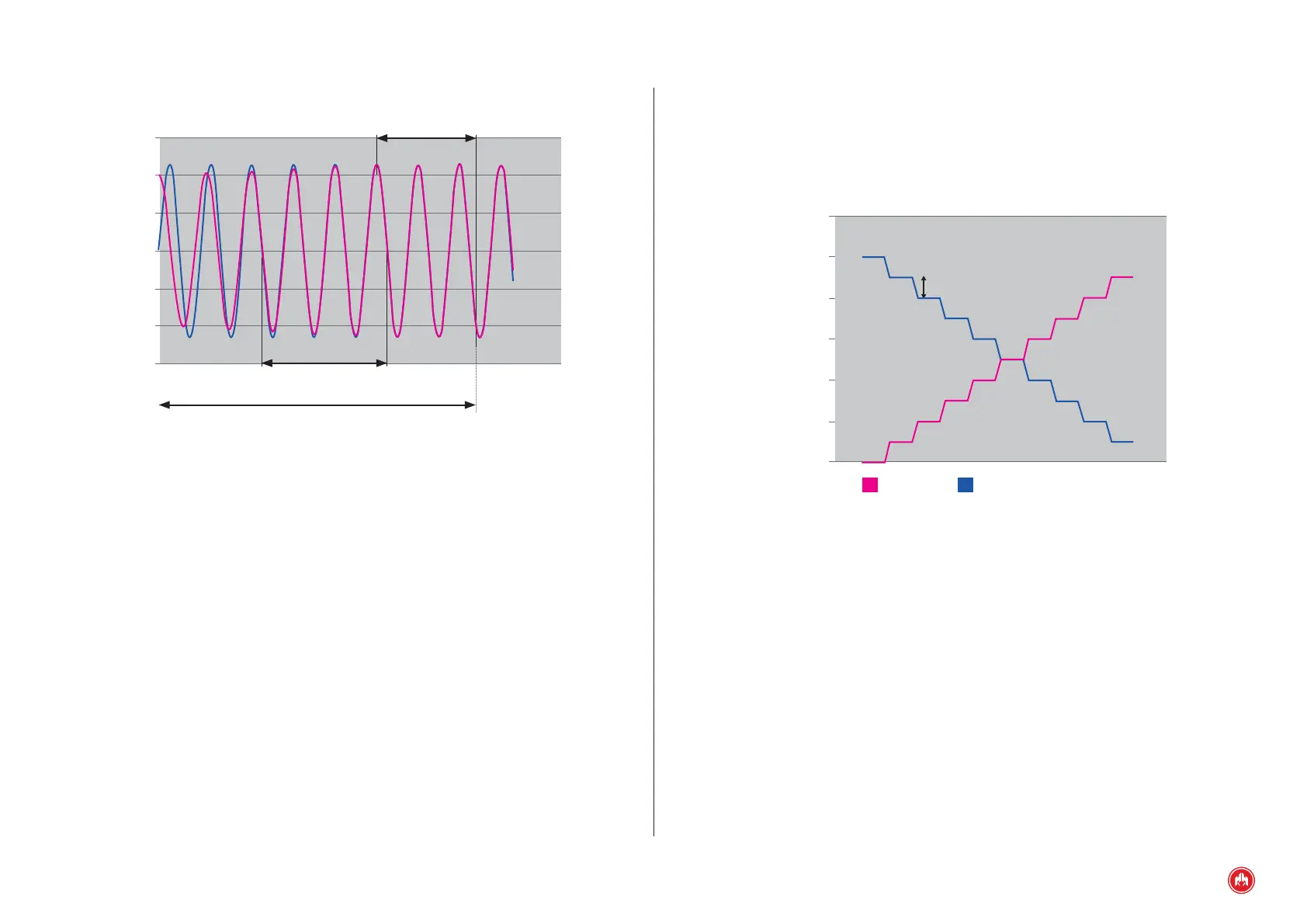
Synchronization Table Parameter 10:
Load transfer factor
Synchronization Table Parameter 9:
Load transfer threshold
GENSET
LOAD TRANSFER FROM NETWORK TO GENSET
MAINS
120
100
80
60
40
20
0
During the load transfer process a control of the generated reactive power is
performed according to a programmed coefcient (Synchronization parameter
table 11).
In the case of failure to achieve synchronization for a maximum programmable
time (Synchronization table parameter 7), the CEC7 control unit depending on its
programming:
• Allowing an interruption of power to the installation during the switching
of the contactors (Synchronization table parameter 8 value1).
• Waiting for user noti cation to reattempt the synchronization between
network and genset signals (Synchronization table parameter 8
value0).
Synchronization Table Parameter 4:
Time synchronized amplitude
Synchronization Table Parameter 5:
No. of Periods of network phase/frequency to validate synchronization
Synchronization time must be less than
Synchronization Table Parameter 7
SYNCHRONIZATION
300
200
100
0
-100
-200
-300
12.2 LOAD TRANSFER
Once the synchronization of genset and network electrical signals has been
achieved, the network and genset contactors are activated. The time elapsed
with the network and genset connectors active simultaneously depends on the
enabling of the load transfer in synchronization:
• If the synchronized load transfer is disabled (Synchronization table,
parameter 9), both contactors will remain active during the programmed
time (Synchronization table, parameter 6).
• If the synchronized load transfer is enabled (Synchronization table,
parameter 9) during the time of simultaneous activation of the network
and genset contactors, the source which assumes the installation load
does so progressively until the source to be disconnected assumes a
load which is lower than the programmed value (Synchronization table
parameter 9).
In order to perform this process, a load transfer factor is programmed
(Synchronization parameter table 10). The higher the factor the faster one source
will shift the load to the other.