(APPENDIX II) CONTROL UNIT SCREENS | PAGE 37
11. APPENDIX II: CEC7 CONTROL UNIT SCREENS
11.1 CONTROL UNIT STATUS
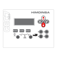
The status of the CEC7 control unit is shown on the display screen, allowing
access to different display options using the up and down navigation keys.
• The current measurement display depends on the con guration of
the current measurement transformers position (Regulations table,
parameter 24).
• Current measurement on output line. The current measurement is
shown on the network or generator screens, depending on which
contactor (network or genset) is active. On screens where the current
measurement does not appear, the numerical value is replaced by a
hyphen.
• Current measurement on network line. The measured intensity is shown
on the display screens of network electrical signal measurements.
11.1.1. NETWORK MEASUREMENT SCREENS
1. Measurements of voltage between phases, the currents of each phase and
genset frequency (integrated mode only - parameter 30, Regulations table, value
0). These voltage measurements are made by the power module of the transfer
switch controller (PHR7).
SWITCHING: 5 0 . 0 H z
V 1 2 2 3 0 V V 1 N 4 0 0 V A
V 2 3 2 3 0 V V 2 N 4 0 0 V A
V 3 1 2 3 0 V V 3 N 4 0 0 V A
2. Measurements of network voltage between the various phases and neutral,

 Loading...