(APPENDIX IV) DIMENSIONS, WIRING AND MECHANICAL PARTS | PAGE 59
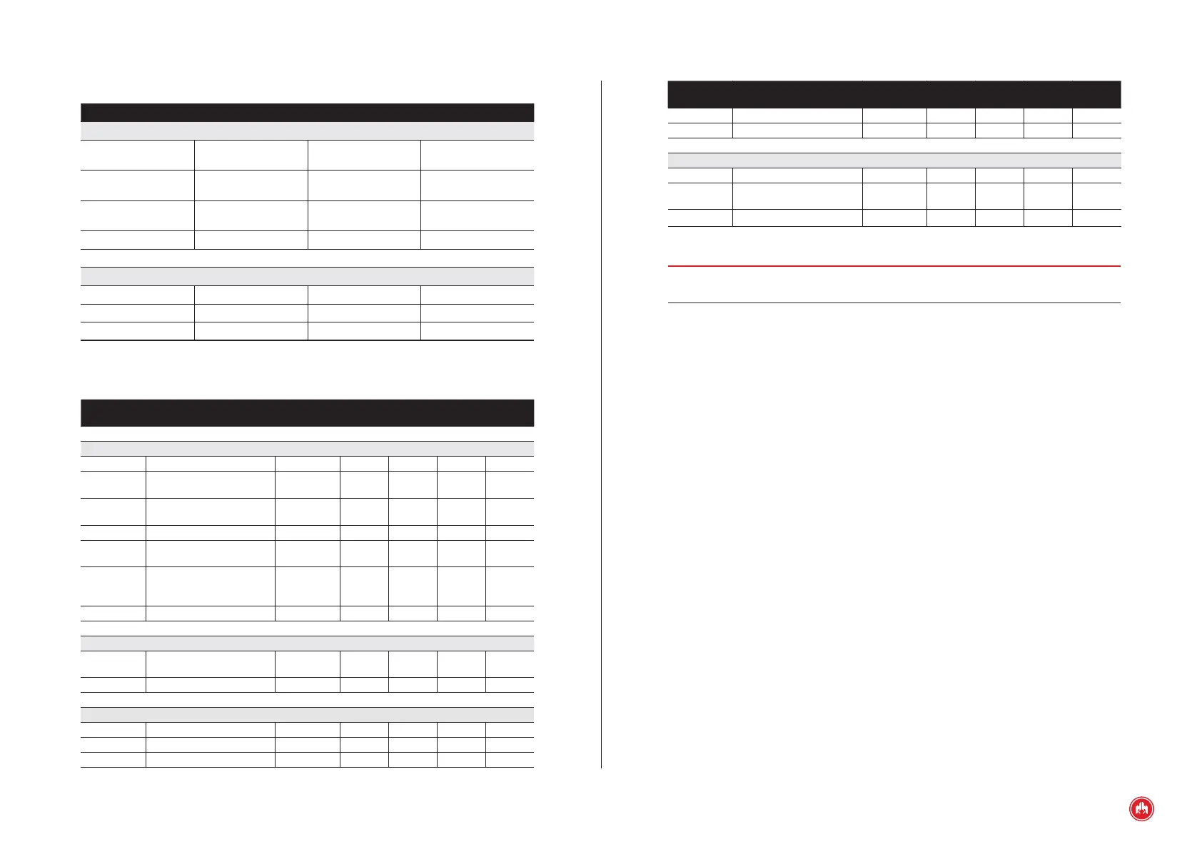
INPUTS AND OUTPUTS
SIGNAL DESCRIPTION TYPE CHARACTERISTICS
POWER SUPPLY
8÷33V Positive battery
terminal
Power supply Module supply voltage
from 8 to 33 V
-BAT Negative battery
terminal
Power supply Module supply neg-
ative
MAN Manual Input Start up PNP digital
input
AUTO Automatic Input PNP digital input
CAN Bus
CANS CAN bus screen CAN Bus CAN communication
CANL L signal of CAN bus CAN Bus CAN communication
CANH H signal of CAN bus CAN Bus CAN communication
ELECTRICAL CHARACTERISTICS
Symbol Parameter Conditions
Mini-
mum
Typical
Maxi-
mum
Unit
Power supply (terminals 8÷33V, –BAT)
8÷33V Power supply voltage 8 33 VDC
I
BAT
Supply current
8÷36 V=12
V
133 mA
I
BAT
Supply current
8÷36 V=24
V
83 mA
P
BAT
Power consumption 2 W
I
BAT
Supply current
8÷36V=12V
heater
1.12 A
I
BAT
Supply current
8÷36 V=24
V
heater
540 mA
P
BAT
Power consumption 13.5 W
CAN Bus (terminals CANS, CANL, CANH)
V
IN
Input voltage in CANH and
CANL
-58 +58 V
DR
CAN
Baud rate 50 Kbps
PNP digital inputs (terminals MAN, AUTO)
V
IN
Input voltage -0.7 33 V
V
IL
Low level input voltage 1 V
V
IH
High level input voltage 5 V
Symbol Parameter Conditions
Mini-
mum
Typical
Maxi-
mum
Unit
IIL Low level input current VIN = 0V 0 100 uA
IIH High level input current VIN = 12V 0.8 1 mA
Environmental conditions and protection of the enclosure
To Operating temperature -20 +60 ºC
HR Relative humidity
No conden-
sation
80 %
IP Degree of Protection *see note1 65
NOTE 1:
IP 65 on the front of the control unit when installed on the control panel with
the sealing gasket provided.
The equipment has been designed and manufactured according to the require-
ments of the directives and harmonized standards which are applicable for com-
pliance with EC regulations.