12
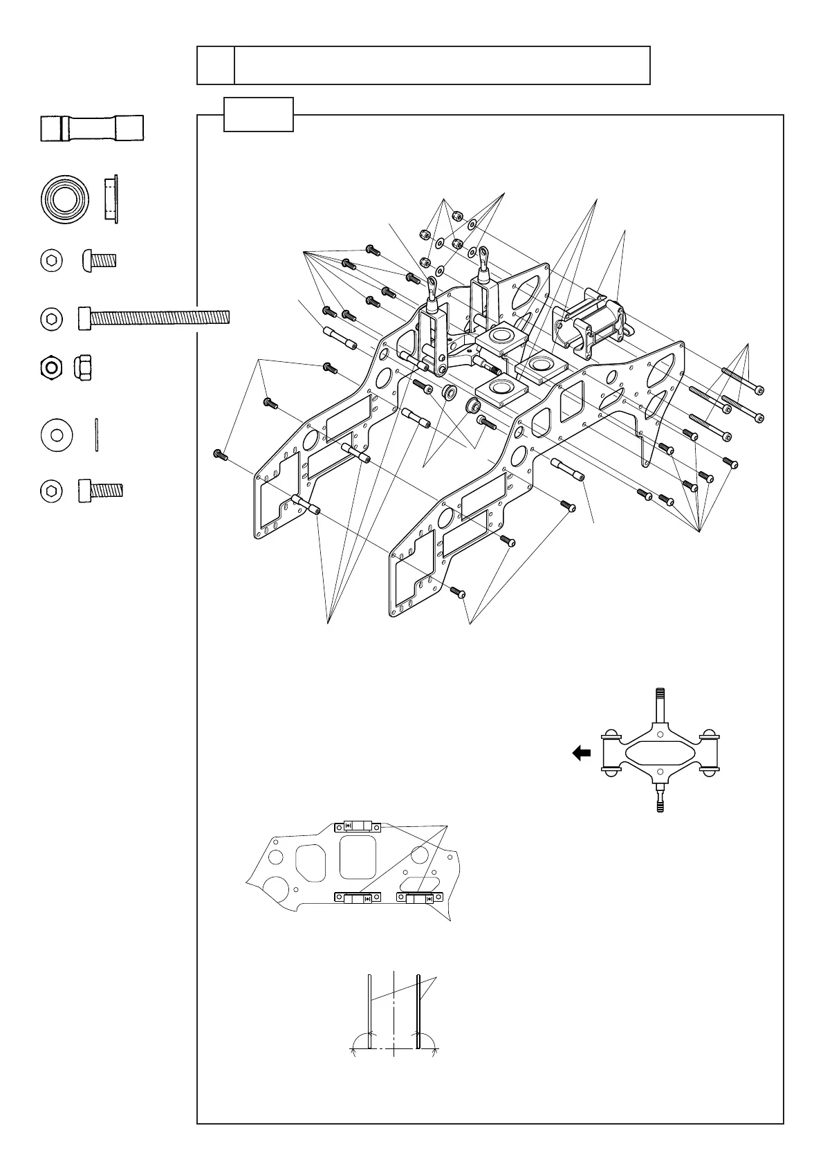
テールブームホルダー
Tailboomholder
M3×6ボタンボルト
M3×6buttonbolt
M3×26クロスメンバー
M3×26crossmember
M3×6ボタンボルト
M3×6buttonbolt
M3×6ボタンボルト
M3×6buttonbolt
M3×35CS(仮組み)
(Temporarily
M3nylonnut
Brg.φ6×φ10×3F
φ3×φ8×0.5FW
φ19Brg.ホルダー(Brg.圧入済)
φ19Brg.holder(Brg.press-fit)
φ19Brg.ホルダー
φ19Brg.holder
φ19Brg.ホルダー取付方向
Directiontoinstallφ19Brg.holder
φ19Brg.ホルダーには取付方向があります。
左図を参考に向きを確認して取り付けてください 。
φ19Brg.holdershouldbeinstalledasspecifieddirection.
Installφ19Brg.holderasshowninthefigureontheleft.
フレームは水平面に対して直角になるよう、ネジを締め
付けてください 。
Tightenthescrewsothatframeispositionedvertically
withhorizontalline.
エレベ ーターレバー
Elevatorlever
注:エレベーターレバーの向き(上から見た図)
Note: Directionofelevatorlever(lookingfromabove)
機首方向
Nose
右
Right
左
Left
M3×8CS
M3×33クロスメンバー
M3×33crossmember
M3×6ボタンボルト
M3×6buttonbolt
M3×33クロスメンバー
M3×33crossmember
M3×35CSは仮組みにし、P27で
テールブームを取 付ける際 締め
付けてください 。
ScrewM3×35CStemporary
first,andtightenthemwhen
installingtailboomwithP27.
90゜90゜
フレーム
Frame
2
アッパーフレームの組立
Assembling the upper frame
STEP 1
φ3×8×0.5FW ............................ 4
M 3 ナイロンナット........................ 4
M3nylonnut
M3×35CS ................................. 4
Brg.φ6×10×3F ........................ 2
M3×26クロスメンバー............... 4
M3×26crossmember
M3×6ボタンボルト................... 20
M3×6buttonbolt
M3×8CS ................................... 2



 To Next Page