16
6
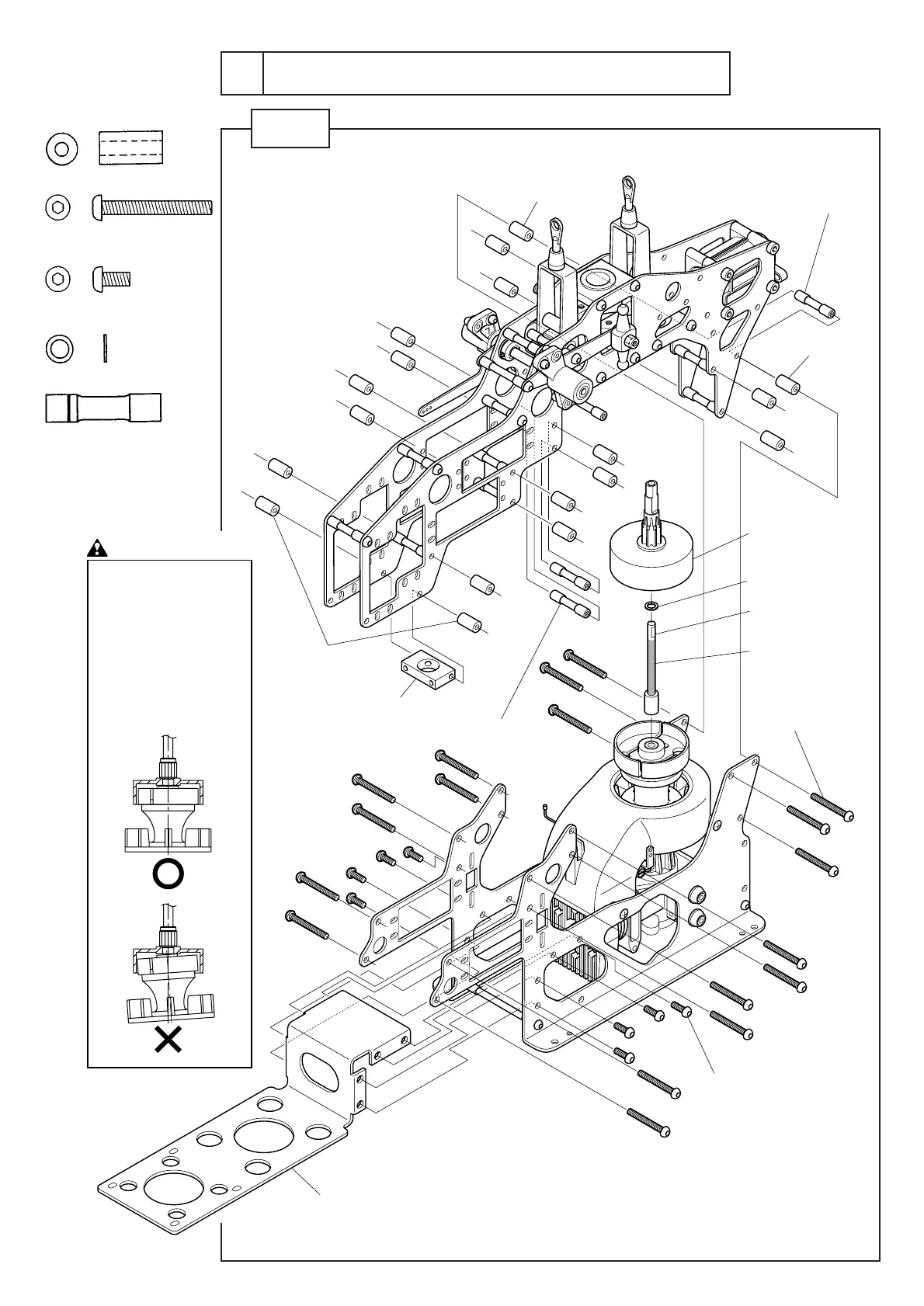
アッパー / ロアーフレームの組立
Combination of the upper and lower frame
STEP 1
M3×6ボタンボルト..................... 8
M3×6buttonbolt
M3×25ボタンボルト................. 18
M3×25buttonbolt
Cφ3×7×14 .............................. 18
φ4×6×0.5FW ............................ 1
M3×26クロスメンバー............... 8
M3×26crossmember
SEクラッチベル
SEclutchbell
φ4×6×0.5FW
スターターシャフトL=64
StartershaftL=64
Cφ3×7×14
Cφ3×7×14
メカプレート
Mechanicalplate
クロスメンバーブロック15×26
Crossmemberblock15×26
グリス塗布
Applygrease
Cφ3×7×14
M3×25ボタンボルト
M3×25buttonbolt
M3×6ボタンボルト
M3×6buttonbolt
M3×2 6 クロスメンバー
M3×2 6 crossmember
M3×2 6 クロスメンバー
M3×2 6 crossmember
注意 Caution
クラッチベ ル の軸とエンジンシ
ャフトが 一 直 線となるように 調
整します 。
エンジンを上 に押し付けた状
態から0.5mm下げて固定して
ください 。
Adjustthecenterlineof
clutchbellshaftand
engineshafttobestraight.
Fixtheengineinaposition
0.5mmlowerthanits
highestpossiblelocation.