Installation GRS1020/1120/1030/1130
Release
03
01/2017
33
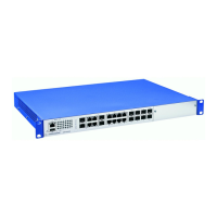
Figure 2: Assembly in a switch cabinet with sliding/mounting rails
1 - GREYHOUND device
2 - sliding/mounting rail
3 - 19" switch cabinet
Proceed as follows:
Assemble the sliding or mounting rails in the 19" switch cabinet as
specified by the manufacturer.
Position the device on the rails in the switch cabinet.
Fasten the device by screwing the brackets to the switch cabinet.
Note: When operating the device in an environment with strong
vibrations, you have the option to additionally fasten the device to the
switch cabinet using 2 holding brackets on the back of the device.
You obtain the additional brackets as accessories.
See “Accessories” on page 54.
P
1
LS
DA
2
3
4
5
6
7
8
M4
-8T
P
-R
J45
LS
DA
LS
DA
LS
D
A
LS
DA
LS
DA
LS
D
A
LS
DA
R
1
LS
DA
2
3
4
5
6
7
8
LS
DA
LS
DA
LS
DA
L
S
D
A
LS
D
A
LS
D
A
LS
DA
P
1
LS/
D
A
2
3
4
5
6
7
8
1
4
7
2
5
8
3
6
M4-F
A
ST 8SFP
P
1
2
3
4
5
6
7
8
1
4
7
2
5
8
3
6
P
P1
P2
P3
P4
RM
RL1
R
L
2
F
A
N
R
U
N
L/
D
FDX
10
00
A
N
T
P
/FO
R
ING
P
OR
T
S
T
B
Y
LE
D
TE
S
T
2
1
1
2
3
4
L
ED
M
E
D
I
A S
L
OTS
M4-A
I
R
S
LO
T
.PO
RT
U
SB
V.
24
6.1
6
.
2
6.3
6
.
4
6
.
5
6.6
6
.
7
6.8
SEL
EC
T
LE
D
MACH
4
0
0
2
48
+
4G
FAULT
R
L
2
L
S
/DA
6
.1
R
L
1
L
S
/
DA
M
4-
FA
ST
8
TP
-
RJ
45
-PoE
M
4
-F
A
S
T
8SF
P
6.1
6.2
6.
3
6
.4 6.
5
6
.
6
6.7
6.8
2
3
1
 Loading...