Installation MACH102
Release
06
09/2014
25
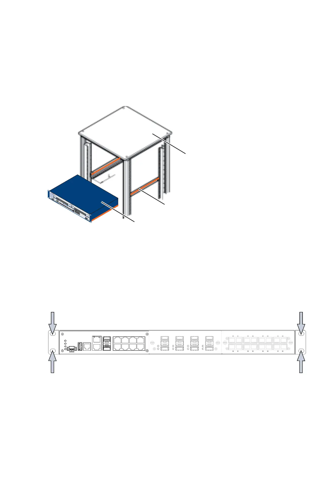
The devices are designed to be mounted in a 19" switch cabinet.
Make sure there is sufficient ventilation. If necessary, provide a fan for
the 19" switch cabinet. This will prevent the basic devices from over-
heating.
Measure the depth of the 19" switch cabinet so as to allow the power
supply cables to be fitted at the back and the data cables to be fitted
at the front.
Install the sliding/mounting rails in the 19" switch cabinet as instructed
by the manufacturer, and make sure the device is resting on both rails.
Figure 15: Assembly in a switch cabinet with sliding/mounting rails
1 - MACH102 device
2 - sliding/mounting rail
3 - 19“ switch cabinet
On delivery, two brackets are attached to the sides of the device (see
figure below).
Figure 16: Mounting the MACH102 in the 19" cabinet
Fasten the device by screwing the brackets to the switch cabinet.
P
1
LS
DA
2
3
4
5
6
7
8
M4-8
TP
-R
J4
5
LS
DA
LS
D
A
LS
DA
L
S
DA
L
S
DA
LS
DA
LS
DA
R
1
L
S
D
A
2
3
4
5
6
7
8
LS
DA
LS DA
LS
DA
LS
DA
LS
DA
L
S
D
A
LS DA
P
1
LS
/
DA
2
3
4
5
6
7
8
1
4
7
2
5
8
3
6
M4-FAST 8SFP
P
1
2
3
4
5
6
7
8
1
4
7
2
5
8
3
6
P
P1
P
2
P3
P4
R
M
RL1
RL2
FAN
RUN
L/D
F
DX
1000
AN
T
P/FO
RING
PORT
S
T
B
Y
LED
T
E
ST
2
1
1
2
3
4
LED
M
EDIA
S
L
O
T
S
M4-AIR
S
LOT.PORT
U
SB
V
.2
4
6.1
6
.2
6
.3
6.4
6
.5
6
.
6
6
.7
6.8
S
ELECT
L
E
D
M
A
CH
40
0
2 48+4G
FAULT
RL2
L
S/D
A
6
.1
RL1
L
S
/D
A
M4-FAST 8TP-RJ45-PoE
M4-FAST 8SFP
6.1
6.2
6.3
6
.4 6.5
6.6
6.7
6.8
2
3
1
MACH 100
LS DA
USB
V.24
MACH 1000
2
1
LS DA
3
4
9
10
P
StandByRM
FAULT
R1
R2
5
6
7
8
13
14
11
12
17
18
15
16
21
22
19
20
25
26
23
24
LS DA
LS DA
LS DA
LS DA

 Loading...