Installation OCTOPUS OS20/OS24 Unmanaged
Release
07
07/2014
27
Note: To protect the exposed contacts of the components still to be installed
from dirt, connect the individual system components in a dry and clean
working area. Seal unused ports with the protection caps available as
accessories.
Install the device in a location where the climatic threshold values
specified in the technical data are adhered to.
Make sure the environment does not heat the device.
Applies to devices with operating voltage type F:
Take care that the temperature of the device base plate remains under
194 °F (90 °C) during operation.
You achieve this, for example, by means of one of the following
measures:
You make sure that the operating voltage of the device is at least 20 V.
You limit the total PoE output to a maximum of 47 W.
You limit the ambient temperature to a maximum of 149 °F (65 °C).
You install the device on a 1.62 ft
2
(0.15 m
2
) metal plate to which you
will connect no other heat sources.
Prepare the drill holes at the installation point.
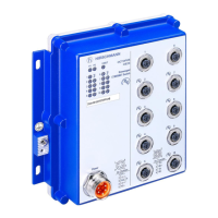
Mount the device on a level surface with four M5 screws.
2.3.2 Grounding the device
The device is grounded via the separate ground screw.
See “Device view” on page 15.
Note: For the ground conductor, use a cable with a cross section of at least
2.5 mm² (North America: AWG12).
Applies to devices with operating voltage type A:
Use the M3 screw for the function ground.
Applies to devices with operating voltage types F and N:
Use the M4 screw for the protective ground.
Use toothed washers to ensure good electrical conductivity at the
connection.
Note: The shielding ground of the connectable twisted pair lines is connected
to the housing as a conductor.
 Loading...
