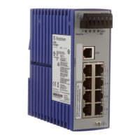
Do you have a question about the Hirschmann MICE MS20 and is the answer not in the manual?
Guidelines for using the device within specified application cases and technical specifications.
Safety requirements for connecting the device to low voltage supply and SELV circuits.
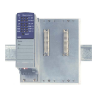
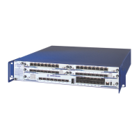
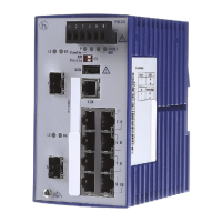
Overview of the MICE basic module and its features for industrial automation.
Explanation of how the product code is structured and its meaning for device properties.
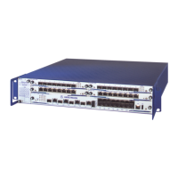
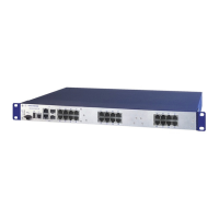
Details on the MICE series, basic modules, and pluggable media modules for network interfaces.
Procedures for verifying package contents and checking for transport damage upon delivery.
Instructions on how to install and remove media modules during operation.
Guidance on using labels for organizing network installation and identifying modules.
Steps for correctly inserting SFP transceivers into the designated slots.
Configuration options for RM, Ring port, and Stand-by using the 4-pin DIP switch.
Configuration options for RM, Ring port, and Stand-by using the 3-pin DIP switch on specific modules.
Settings for SQE test and DTE voltage monitoring on the MM20 media module.
Instructions for connecting the PoE media module and its power supply.
Details on connecting supply voltage and signal contacts via terminal blocks.
Procedures for connecting terminal blocks and initiating the device's operation.
Instructions for mounting the device on a DIN rail and proper grounding methods.
Guidance on connecting various types of data lines to the device ports.
Steps for assembling and installing the MB20 extender module.
How to use the SELECT button to interpret the meaning of media module LEDs.
Overview of the factory default IP address, passwords, data rate, and port configurations.
Information about the USB socket for connecting an AutoConfiguration Adapter for software updates.
Details on the serial interface for connecting external management stations or adapters.
Guidelines for operating the device within specified ambient temperature limits.
Steps for detaching the device from the mounting rail.
Instructions for safely extracting SFP transceivers from their slots.
Comprehensive technical specifications for the MS20/MS30 devices.
Standards and compliance levels for electromagnetic emissions from the device.
Standards and compliance levels for conducted interference affecting the device.
Immunity levels against electrostatic discharge as per relevant standards.
Immunity levels against electromagnetic fields as per relevant standards.
Immunity levels against fast transients on power and data lines.
Immunity levels against voltage surges on power and data lines.
Immunity levels against damped vibrations on device connections.
Immunity levels against impulse-shaped magnetic fields.
Device resistance to vibration and shock according to IEC standards.
Maximum cable length for the Attachment Unit Interface (AUI) port.
Maximum cable lengths for twisted pair Ethernet ports (10/100/1000BASE-T).
| Brand | Hirschmann |
|---|---|
| Model | MICE MS20 |
| Category | Network Router |
| Language | English |
