40
Installation MS20/MS30
Release
11
07/2013
2.10 Connecting the terminal blocks, start-up
procedure
Pull the terminal block off the device and connect the voltage supply lines
and the signal lines.
2.10.1 Terminal blocks on MS20/MS30-...A... and
MS20/MS30-...C...
Products with voltage range A or C (product code position 15—see table 1)
have two 4-pin terminal blocks.
Note: The maximum accaptable wire size for the terminal blocks is 2.5 mm
2
(0.004 in
2
) or AWG 12.
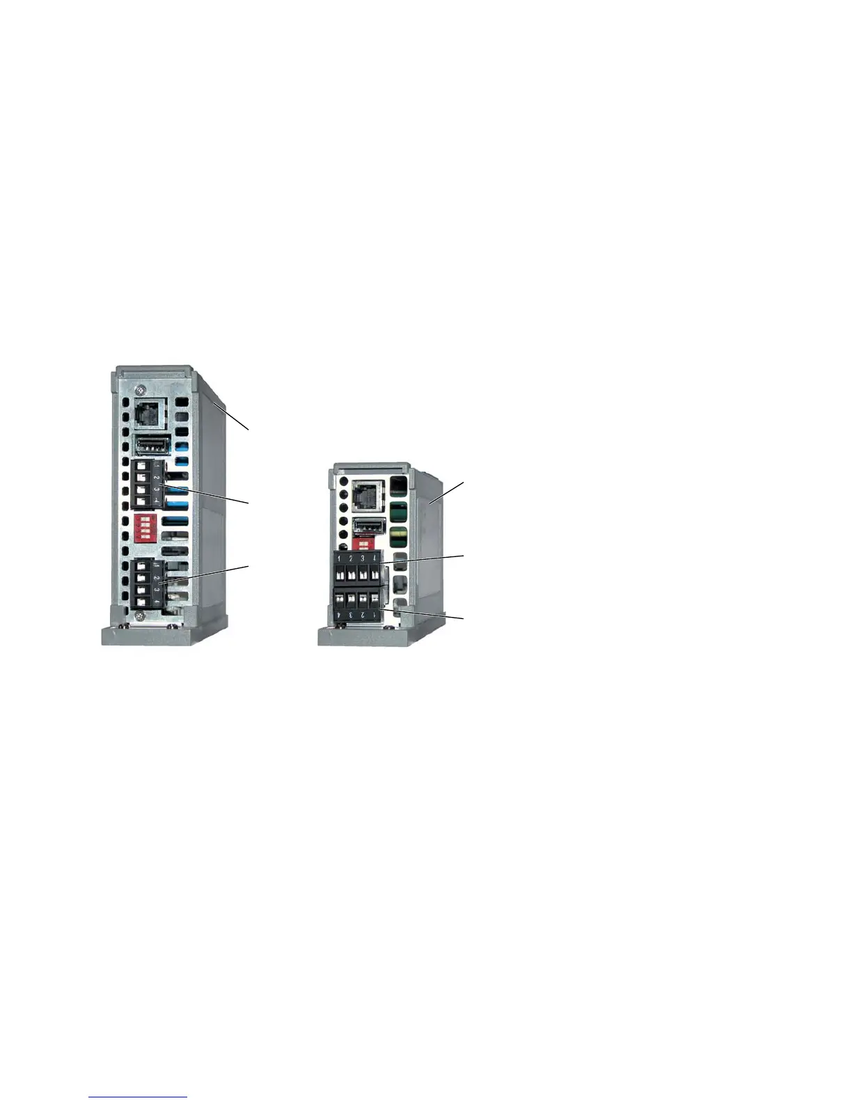
Figure 16: Pin assignment of the 4-pin terminal blocks
1 - MS20/30 switch basic module with 18 V DC ... 60 VDC voltage range
2 - Power/signal contact 1:
Pin 1 =+24 V (P1), Pin 2 =0 V, Pin 3, 4 =Relay 1
3 - Power/signal contact 2:
Pin 1 =+24 V (P2), Pin 2 =0 V, Pin 3, 4 =Relay 2
4 - MS20/30 switch basic module with 18 to 32 VDC voltage range
5 - Power/signal contact 1:
Pin 1 =+24 V (P1), Pin 2 =0 V, Pin 3, 4 =Relay 1
6 - Power/signal contact 2:
Pin 1 =+24 V (P2), Pin 2 =0 V, Pin 3, 4 =Relay 2