a. Place the drain hose under the pipes.
b. Insulation material uses polythene foam over
6mm in thickness.
Note: Drain hose is prepared by user.
Drain pipe should point downward for easy drain
flow. Do not arrange the drain pipe twisted,
sticking out or wave around, do not immerse the
end of it in water.
If an extension drain hose is connected to the drain
pipe, make sure to thermal insulated when passing
along the indoor unit.
When the pipes is directed to the right, pipes, power
Cord and drain pipe should be thermal insulated and
fixed onto the back of the unit with a pipe fixer.
Piping Connection:
Drain hose:
If you don't hear the exhaust noise,
please contact with the merchant.
a.Before unscrewing the big and the
small sealing caps, press the small
sealing cap with the finger until the
exhaust noise stops, and then
loosen the finger.
b.Connect indoor unit pipes with
two wrenches. Pay special attention
to the allowed torque as shown
below to prevent the pipes,
connectorsand flare nuts from being
deformed and damaged.
c. Pre-tighten them with fingers at
first, then use the wrenches.
Pipe size
Model
Liquid Side ( 1/4 inch) φ6mm or
5k~12K,13k~18K,21 K~24
12K , 13K~18K
#
18K , 21K~36K
#
18K , 21K~36K
#
5K~13K
15~20N·m
17mm
0.5mm
0.6mm
0.6mm
0.6mm
0.6mm
22mm
24mm
22mm
27mm
30~35N·m
30~35N·m
50~55N·m
60~65N·m
Liquid Side ( 3/8 inch)φ9.53mm or
Gas Side ( inch)φ12mm or 1/2
Gas Side ( 3/8 inch)φ9.53mm or
Gas Side ( 5/8 inch)φ16mm or
Torque
Nut width Min.thickness
1.0mm
36K
#
32mm
Gas Side ( 3/4 inch)φ19mm or
70~75N·m
Note: Piping connection should be conducted on outdoor
side !
For Inverter appliance
For ON-OFF appliance
Note: The unit of 12K ,18K ,24K ,36K is bigger than the unit of
12K,18K,24K,36K.
# # # #
Pipe size
Model
Liquid Side ( 1/4 inch) φ6mm or
5 12K,13 18K,21 24K~ ~ ~
12 ,14,15,18K
#
K
18K ,22,24K ,28,30,36K
# #
18K ,22,24,28,30,36K
#
36K
#
5 10K~ ,12K
15~20N·m
17mm
0.5mm
0.6mm
0.6mm
0.6mm
0.6mm
22mm
24mm
22mm
27mm
30~35N·m
30~35N·m
50~55N·m
60~65N·m
Liquid Side ( 3/8 inch)φ9.53mm or
Gas Side ( inch)φ12mm or 1/2
Gas Side ( 3/8 inch)φ9.53mm or
Gas Side ( 5/8 inch)φ16mm or
Torque
Nut width Min.thickness
1.0mm
32mm
70~75N·m
Gas Side ( 3/4 inch)φ19mm or
Indoor Unit Installation
# # #
Note: The unit of 12K ,18K and 36K is bigger than the unit of 12K,
18K and 36K.
Hanging wallboard
Accessory
hose
Connecting cord
Drain hose
Fresh air hose
Fig. 13
Fig. 14
9
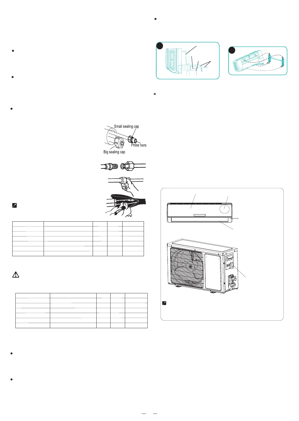
Pass the wrapped hose out of the wall hole, and move
the indoor side hose line together with the indoor unit
to the corresponding position of the hanging
wallboard (Figure 13).
Hang the two mounting grooves above the indoor unit
on the fixing claws of the hanging wallboard, and
move the machine body horizontally to check whether
the fixing is firm
Grasp both sides of the machine body with both
hands, and press the indoor unit against the
hanging wallboard, so that the bottom is firmly
connected (Figure 14).
Access door
Terminal(inside)
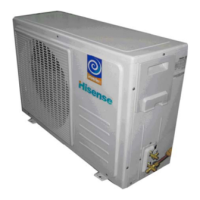
Outdoor unit
The figures in this manual are based on the external
view of a standard model. Consequently, the shape
may differ from that of the air conditioner you have
selected.
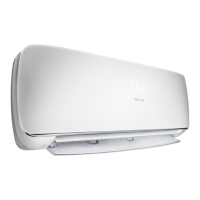
Chassis
Cabinet
Front panel
Terminal (inside)
Indoor unit
Caution:
1. Never fail to have an individual power circuit specifically
for the air conditioner. As for the method of wiring, refer to
the circuit diagram posted on the inside of the access door.
2. Comfirm that the cable thickness is as specified in the
power source specification.
3. Check the wires and make sure that they are all tightly
fastened after cable connection.
4. Be sure to install an earth leakage circuit breaker in wet or
moist areas.
4. Connecting of the Cable
Outdoor Unit
1) Remove the access door from the unit by
loosening the screw. Connect the wires to the
terminals on the control board individually as
follows.
2) Secure the power cord onto the control
with cable clamp.
board
.
3) Reinstall the access door to the original position
with the screw.
4) Use a recognized circuit breaker for 24K model
between the power source and the unit. A
disconnecting device to adequately disconnect all
supply lines must be fitted.