Digital Main P.W.B has five LED (KNIGHT RIDER) on board.
After Power ON
these LED will be turned on in sequence as follows.
It may take a few seconds for the sequence.
LED sequence
Sequence D
205
(Red)
<PiO04>
D
204
(Green)
<PiO03>
D
203
(Yellow)
<PiO02>
D
202
(Orange)
<PiO01>
D
201
(Red)
<PiO00>
1 (Start)
○○ ○○●
2
○○ ○●●
3
○○ ●●●
4
○●●●●
5 (End)
○○○○
○
○
is turn off the LED,
●
is Lighting the LED
After Program is loaded without error, all LED will be turned off.
Any LED should not light.
If some errors occur, LED will show the error pattern.
(1) Check that LED is not lit.
(2) If LED is lit, refer to the following table and check the involved devices.
TROUBLE SHOOTING for DIGITAL MODULE (Device error check)
TABLE OF CONTENTS
TROUBLESHOOTING FLOW CHARTS
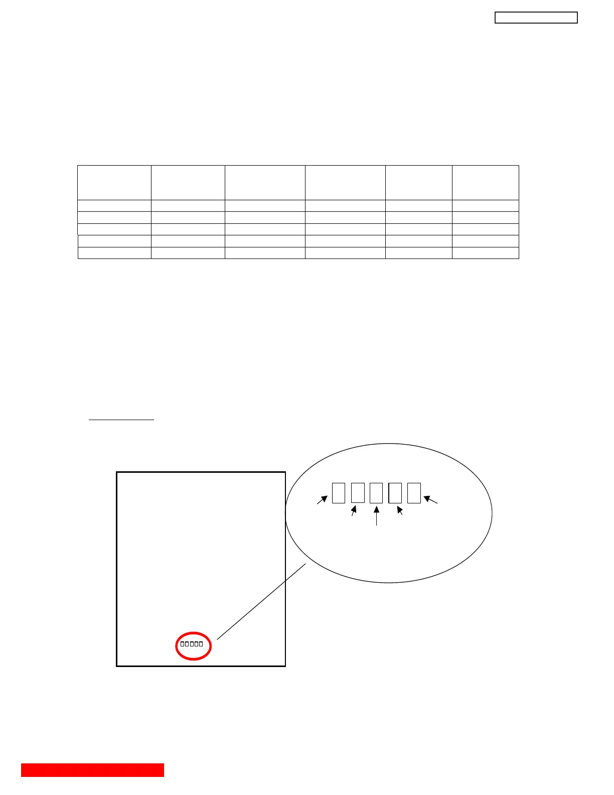
Location of LEDs
Digital Main Board
LED5 (D205) LED1(D201)
LED4 (D204) LED2 (D202)
LED3 (D203)
(42” only)
51
DW2U
 Loading...