English
— 18 —
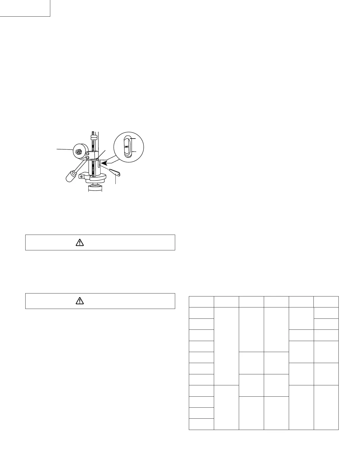
REMOVING CHUCK AND ARBOR (FIG. U)
1. With the switch “OFF” and the unit unplugged, adjust
the depth stop nut (1) to hold the drill at a depth
of three inches. (See instructions for “LOCKING
CHUCK AT DESIRED DEPTH”).
2. Align the key holes in the spindle (2) and quill (3) by
rotating the chuck by hand.
3. Insert the key wedge (4) into the key holes (2 & 3).
4. Tap the key wedge (4) lightly with a plastic tipped
hammer, until the chuck and arbor fall out of the
spindle.
NOTE: Place one hand below the chuck to catch it
when it falls out.
Fig. U
2
3
4
1
BASIC OPERATION INSTRUCTIONS
To get the best results and minimize the likelihood of
personal injury, follow these instructions for operating
your drill press.
WARNING
For your own safety, always observe the SAFETY
INSTRUCTIONS listed here and on pages 4, 5 & 6 of the
instruction manual.
YOUR PROTECTION
WARNING
To avoid being pulled into the power tool, do not wear
loose clothing, gloves, neckties, or jewelry. Always tie
back long hair.
1. If any part of your drill press is missing,
malfunctioning, damaged or broken, stop operation
immediately until that part is properly repaired or
replaced.
2. Never place your fi ngers in a position where they
could contact the drill bit or other cutting tool. The
workpiece may unexpectedly shift, or your hand
could slip.
3. To avoid injury from parts thrown by the spring, follow
instructions exactly when adjusting the spring tension
of the quill.
4. To prevent the workpiece from being torn from your
hands, thrown, spun by the tool, or shattered, always
properly support your workpiece as follows:
a. Always position BACKUP MATERIAL (used
beneath workpiece) so that it contacts the left side
of the column.
b. When using a drill press vise, always fasten it to
the table.
c. Never do any work freehand (hand-holding the
workpiece rather than supporting it on the table),
except when polishing.
d. Securely lock the head and support to the column,
the table arm to the support, and the table to the
table arm, before operating the drill press.
e. Never move the head or the table while the tool is
running.
f. Before starting an operation, jog the motor switch
to make sure the drill or other cutting tool does not
wobble or cause vibration.
g. If a workpiece overhangs the table so it will fall
or tip if not held, clamp it to the table or provide
auxiliary support.
h. Use fi xtures for unusual operations to adequately
hold, guide, and position workpieces.
i. Use the SPINDLE SPEED recommended for
the specifi c operation and workpiece material.
Check the panel on the inside pulley cover or the
chart below for drilling speed information. For
accessories, refer to the instructions provided with
each accessory.
5. Never climb on the drill press table, it could break or
pull the entire drill press down on you.
6. Turn the motor switch “OFF”, and put away the switch
key when leaving the drill press.
7. To avoid injury from thrown work or tool contact, do
not perform layout, assembly, or set up work on the
table while the cutting tool is rotating.
DRILLING SPEED CHART
FOR USE WITH HIGH SPEED TWIST DRILLS
Material
Drill Dim.
mm
Wood Aluminum Plastic Mild Steel Stainless
0.8 2580 2580 2580 2580 2580
1.6 1580-2580
3 1580-2580 830-1580
5 830-1580 500-540
6 1580-2580 1580-2580
8 500-540 320-500
10 830-1580 830-1580
11 1580-2580 320-500 210
13 500-540 500-540
14
16
000BookB16RM.indb18000BookB16RM.indb18 2015/01/1410:56:462015/01/1410:56:46
 Loading...