--- 38 ---
(4) Adjustment of the laser marker
Adjust the laser marker according to the following steps from to .
Adjust the product accuracy first because the accuracy of the laser marker is adjusted aligning the cut surface
of the workpiece.
Make a right-angle ink line on the workpieces of 38 mm in
height and 89 mm in width. Adjust the laser marker and
perform cutting. If the ink line matches the cutting position,
the accuracy adjustment is completed. (Visually check that
the laser marker accuracy is 0.5/100 or less for both the
squareness with the base surface and the squareness with
the fence surface.)
To check the accuracy of the laser marker, move the laser
marker horizontally using the special bolt M5 again and
check that the laser beam is applied to the entire cutting
surface. If the laser beam is applied to the cutting surface in
parallel, the fine fuzz reflects the laser beam and the entire
cutting surface becomes bright.
Turn the hex. socket set screw M5 x 6 and the minus groove
at the rear of laser holder (A) so that laser beam is applied to
the entire cutting surface of the workpiece.
If the laser line gets out of the cutting surface during the laser
line adjustment, turn the special bolt M5 to shift the laser line
onto the cutting surface, top edge or rear edge of the cutting
surface then adjust the accuracy of the laser line. (Repeat
this operation 3 or 4 times depending on the adjusting
conditions of the laser marker.) Refer to the above (2) and (3)
for the relation between the hex. socket set screw M5 x 6
and the laser line, and the relation between the minus groove
at the rear of laser holder (A) and the laser line.
First, hold a workpiece of 38 mm in height and 89 mm in
width with the vise and perform right-angle cutting.
Light up the Laser Marker with the workpiece held in the
vise. Turn the special bolt M5 to shift the laser line onto the
cutting surface, top edge or rear edge of the cutting surface.
1
2
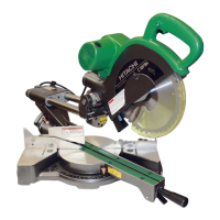
Cut the workpiece and light
up the laser marker.
Laser emitting
aperture
Laser beam
Fig. 44
Cutting surface
3
4
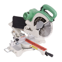
Turn the special bolt M5 to shift the laser line
onto the cutting surface, top edge or rear
edge of the cutting surface.
Laser line
Top edge of the
cutting surface
Fig. 45
Cutting surface
Rear edge of
the cutting
surface
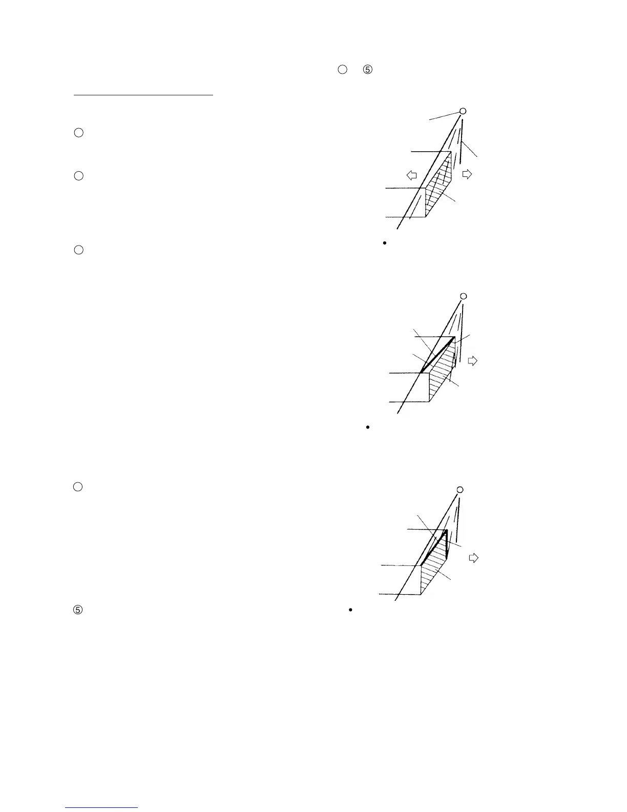
Adjust the hex. socket set screw M5 x 6 and
the minus groove at the rear of laser holder (A)
or the special bolt M5 to apply laser beam to
the entire cutting surface.
Laser line
Fig. 46
Cutting surface
Laser line
1
 Loading...