13
English
BEFORE CUTTING
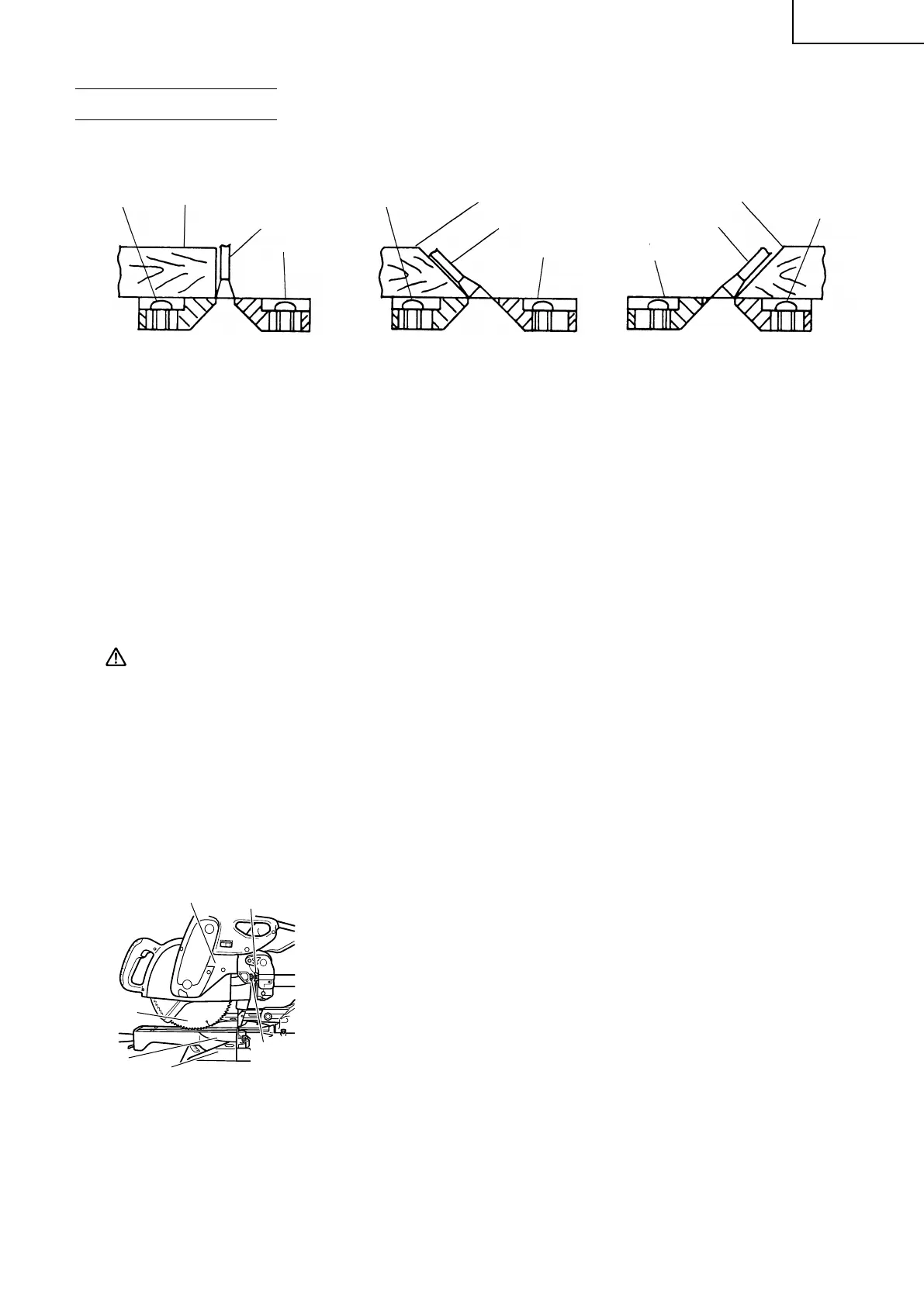
1. Positioning the table insert
[Right angle cutting] [Left bevel angle cutting] [Right bevel angle cutting]
Fig. 8-a Fig. 8-b Fig. 8-c
Table inserts are installed on the turntable. When shipping the tool from the factory, the table inserts
are so fixed that the saw blade does not contact them. The burr of the bottom surface of the workpiece
is remarkably reduced, if the table insert is fixed so that the gap between the side surface of the table
insert and the saw blade will be minimum. Before using the tool, eliminate this gap in accordance with
the following procedure.
(1) Right angle cutting
Loosen the three 6mm machine screws, then secure the left side table insert and temporarily tighten
the 6mm machine screws of both ends. Then fix a workpiece (about 7-7/8" (200mm) wide) with the
vise assembly and cut it off. After aligning the cutting surface with the edge of the table insert,
securely tighten the 6mm machine screws of both ends. Remove the workpiece and securely tighten
the 6mm center machine screw. Adjust the right hand table insert in the same way.
(2) Left and right bevel angle cutting
Adjust the table insert in the manner shown in Fig. 8-b and Fig. 8-c following the same procedure for
right angle cutting.
CAUTION: After adjusting the table insert for right angle cutting, the table insert will be cut to
some extent if it is used for bevel angle cutting.
When bevel cutting operation is required, adjust the table insert for bevel angle cutting.
2. Checking the saw blade lower limit position
Check that the saw blade can be lowered 13/32" to 7/16" (10mm to 11mm) below the table insert as
shown in Fig. 9.
When you replace a saw blade with a new one, adjust the lower limit position so that the saw blade will
not cut the turntable or complete cutting cannot be done.
To adjust the lower limit position of the saw blade, follow the procedures (1) to (4) indicated below. (Fig.
10)
Furthermore, when changing the position of a 8mm depth adjustment bolt that serves as a lower limit
position stopper of the saw blade, it becomes necessary to shift the position of a 8mm hexagon socket
set screw that is in the screw hole for the 8mm depth adjustment bolt that serves as the stopper.
(1) Loosen the 8mm wing nut.
(2) Insert your 6mm hexagon bar wrench from behind of the tool
and turn the 8mm hexagon socket set screw to the left
(counterclockwise) as viewed from behind of the tool.
(3) Turn the 8mm depth adjustment bolt, change the height where
the bolt head and the gear case contacts, and adjust the lower
limit position of the saw blade. One turn of the 8mm depth
adjustment bolt changes the lower limit position of the saw
blade by about 5/16"(8mm), and this information can be used
as a rough guide.
Table insert
Workpiece
Workpiece
Table insert
Saw Blade
Workpiece
Table insert
Saw Blade
Saw Blade
6mm
Machine
Screw
6mm
Machine
Screw
6mm
Machine
Screw
Gear Case
Base
8mm Wing Nut
8mm Depth
Adjustment
Bolt
Saw Blade
Turntable
Fig. 9
01Eng_C10FSH_Eng_Spa 09/3/19, 16:4613

 Loading...