22
English
10. Crown molding cutting procedures
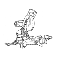
Fig. 33 shows two common crown molding types having angles of (θ) 38° and 45°.
For the typical crown molding fi ttings, see Fig. 34.
Wall
upper surface
Ceiling
lower surface
Ceiling
Wall
1
2
34
Inside corner Outside corner
⎫
⎬
⎭
⎫
⎬
⎭
Fig. 34Fig. 33
The table below shows the miter angle and the bevel angle settings that are ideal for the two crown molding
types.
NOTE:
For convenience, positive stops are provided for the miter setting (left and right 31.6°) positions.
For miter cut setting
If the turntable has been set to either of the angles described, move the turntable adjusting side handle a little
to the right and left to stabilize the position and to properly align the miter angle scale and the tip of the indicator
before the operation starts.
For bevel cut setting
Move handle on bevel section to the left and check that the position is stable and that the bevel angle scale
and the tip of the indicator are properly aligned. Then tighten the clamp lever.
Type of Crown
Molding
To process crown molding at positions
1 and 4 in Fig. 34.
To process crown molding at positions
2 and 3 in Fig. 34.
Miter Angle
Setting
Bevel Angle
Setting
Miter Angle
Setting
Bevel Angle
Setting
45° Type
right 35.3°
(
mark)
left 30°
( mark)
left 35.3°
( mark)
left 30°
( mark)
38° Type
right 31.6°
(
mark)
left 33.9°
( mark)
left 31.6°
( mark)
left 33.9°
( mark)
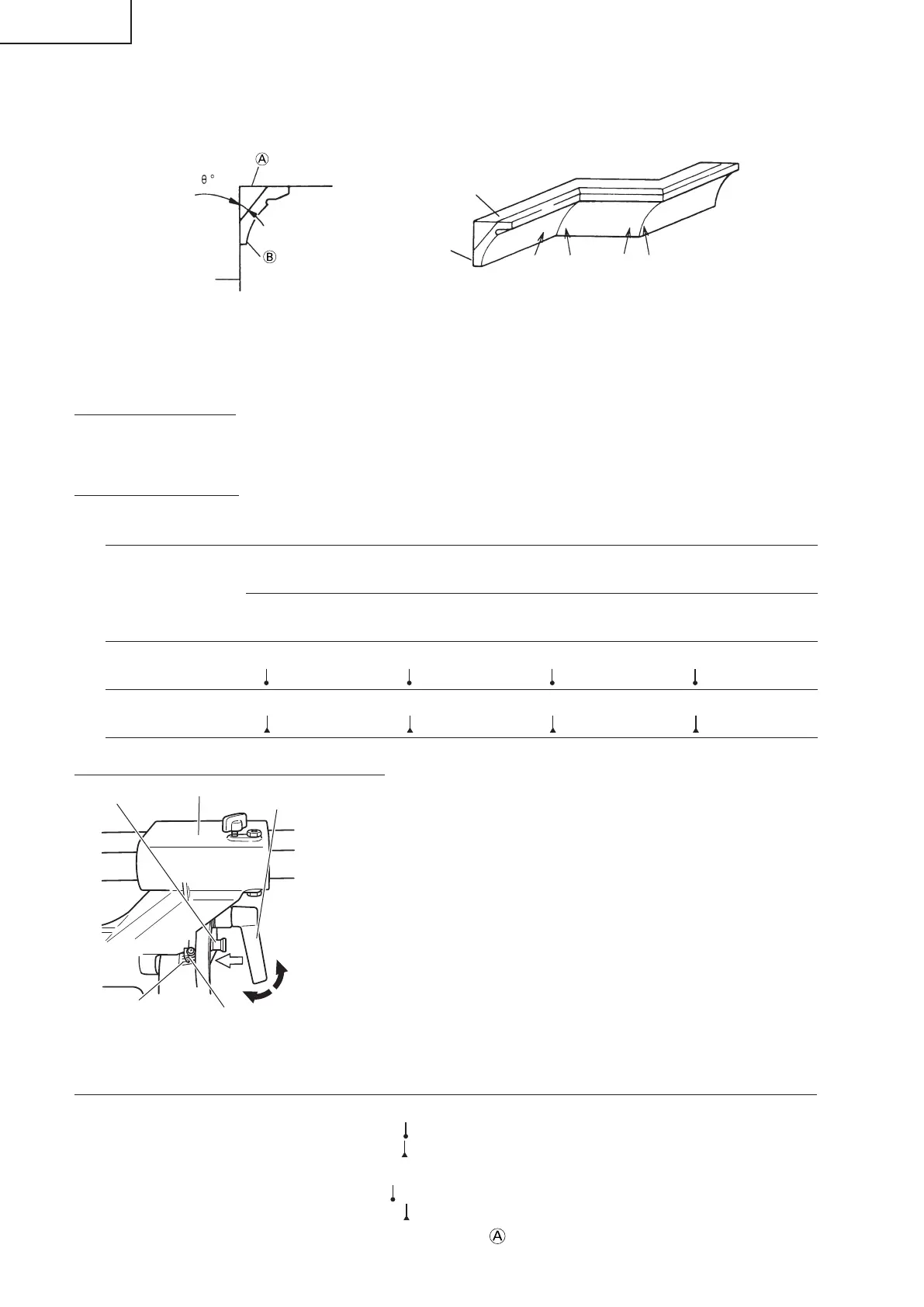
30° and 33.9° left slant setting method
(1) Loosen the clamp lever and slant to the left a little at a time while pushing
the fi xing pin into the main unit. At this time, the fi xing pin will enter one
step and fi t into the 30° left slant and 33.9° left slant setting slots.
(2) With the fi xing pin in the slot as described above, setting to the 30° left
slant position is possible by pushing to the right side.
(3) Also, with the fi xing pin in the slot as described above, setting to the
33.9° left slant position is possible by pushing to the left side.
(4) Look at the bevel scale and indicator to recheck whether or not the
settings match and then tighten the clamp lever.
(1) Setting to cut crown moldings at positions 1 and 4 in Fig. 34 (see Fig. 36; tilt the motor head to the left):
1 Turn the turntable to the right and set the Miter Angle as follows:
* For 45° type crown moldings: 35.3° (
mark)
* For 38° type crown moldings: 31.6° (
mark)
2 Tilt the motor head to the left and set the Bevel Angle as follows:
* For 45° type crown moldings: 30° (
mark)
* For 38° type crown moldings: 33.9° (
mark)
3
Position the crown molding so that the upper surface ( in Fig. 33) contacts the fence as indicated in Fig. 38.
Fixing pin
Holder (A)
Clamp Lever
Tighten
Push
Indicator
(for left bevel scale)
Bevel Scale
Fig. 35
Loosen
0000BookC10FSH.indb220000BookC10FSH.indb22 2015/08/1015:19:182015/08/1015:19:18

 Loading...