P5417025-rev.1
23
4231 4231 4231
3
ON
56412 1
ON
3421
ON
2
1
ON
21
ON
21
ON
21
ON
2
1
ON
2
3
ON
56412 1
ON
3421
ON
2
1
ON
21
ON
21
ON
21
ON
2
1
ON
2
PCN2PCN1
LED2
LED1
LED4 LED5
LED6
LED7
LED3
DSW3DSW2DSW1
TP
CN11
DSW8
DSW7
DSW6
DSW5
DSW4
CN9 CN10
CN8CN7
CN6CN5CN4
CN12
LED17
LED16
LED15
LED14
LED13
LED12
LED11
LED10
CN1 CN2 CN3
PCN2PCN1
LED2
LED1
LED4 LED5
LED6
LED7
LED3
DSW3DSW2DSW1
TP
CN11
DSW8
DSW7
DSW6
DSW5
DSW4
CN9 CN10
CN8CN7
CN6CN5CN4
CN12
LED17
LED16
LED15
LED14
LED13
LED12
LED11
LED10
CN1 CN2 CN3
3
ON
56412 1
ON
3421
ON
2
1
ON
21
ON
21
ON
21
ON
2
1
ON
2
PCN2PCN1
LED2
LED1
LED4 LED5
LED6
LED7
LED3
DSW3DSW2DSW1
TP
CN11
DSW8
DSW7
DSW6
DSW5
DSW4
CN9 CN10
CN8CN7
CN6CN5CN4
CN12
LED17
LED16
LED15
LED14
LED13
LED12
LED11
LED10
CN1 CN2 CN3
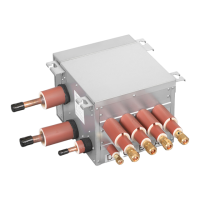
Control Wiring Connection
(3 x φ26mm [1 inch])
Power Supply Wiring Connection
(φ26mm [1 inch])
Cable Clamp
Cable Clamp
Clamp
(Accessory (7))
Communication Cable
Communication cable between
the outdoor unit and CH-Box.
Cable Clamp
Clamp
(Accessory (7))
Cable Clamp
Clamp
Terminal Block
for Power Supply
Ground Terminal
Terminal Blocks for Communication
between CH-Box and Indoor Unit
Wire Clip
(Use to
route wiring)
DCBAHGF
KJI
TB1
PCB3PCB2PCB1
TB2
TB3TB4 TB3TB4 TB3TB4
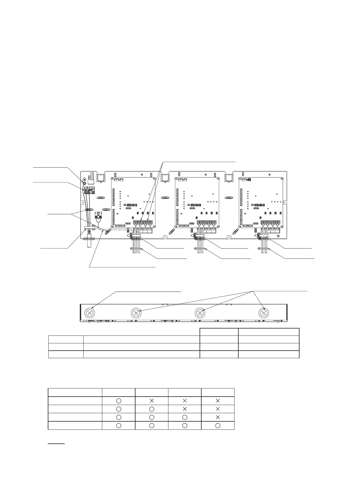
Figure6.1ElectricalWiringConnection
6.3 ElectricalWiring
TheelectricalwiringconnectionfortheCH-BoxisshowninFigure6.1.
(1) TurnOFFthemainpowerswitchandtakeofftheelectricalboxcoverofCH-Box.
(2) ConnectthepowersupplywiringtoL1andL2ontheterminalblockTB1,andconnectgroundwiringto
theterminalsintheelectricalbox.
(3) ConnectthecommunicationcablebetweentheoutdoorunitandCH-BoxtoTB2oftheCH-Box.
ConnectthecommunicationcablebetweentheCH-BoxandindoorunittoTB3andTB4ofthe
CH-Box.
EnsurethatthecommunicationcablebetweentheCH-Boxandindoorunitisconnectedtothesame
letteraspipingconnection.(TighteningTorque:1.0to1.3N
.
m(0.7to1.0ft
.
lbs))
Referto“ExampleofElectricalWiring”forthewiringconnection.
(4) Tightlyclampthewiresusingthecableclampinsidetheelectricalbox.
(5) Makesurethecommunicationcablesoutsidetheelectricalboxdoesnottouchsharpedgesby
securingwithclamp(accessory(7)).
(6) Attachtheelectricalboxcoveraftercompletingthewiringwork.
NOTE:
TheaccessorynumbersarelistedinTable4.1.
AbovegureillustratetheexampleofCH-AP12MSSX.
NumberofPCBsaredifferentdependingonmodelnumber.
Refertothefollowingtable.
PCB1 PCB2 PCB3 PCB4
CH-AP06MSSX
CH-AP08MSSX
CH-AP12MSSX
CH-AP16MSSX
ScrewSize TighteningTorque
TB1 TerminalBlockforPowerSupplyCable M4 1.0~1.3N.m
TB2 TerminalBlockforCommunicationCable M3.5 0.7~0.9N.m
TB3,TB4 TerminalBlockforCommunicationCable M4 1.0~1.3N.m