EasyManua.ls Logo

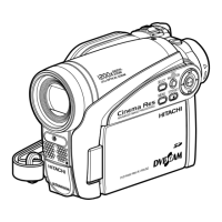
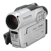
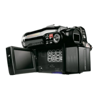
Hitachi DZ-GX5020A User Manual

Hitachi DZ-GX5020A
154 pages
To Next Page IconTo Next Page
Page #1 background imageLoading...
Page #1 background image
SERVICE MANUAL
SPECIFICATIONS AND PARTS ARE SUBJECT TO CHANGE FOR IMPROVEMENT
No. 0614E
DVD VIDEO CAMERA/RECORDER
TK
DZ-GX5080A
DZ-GX5020A
DZ-GX5020A (K)
DZ-GX5000A
DO NOT RESELL OR DIVERT IMPROPERLY
DZ-GX5080A
DZ-GX5000A
DZ-GX5020A
December 2006

Table of Contents

Questions and Answers:

Hitachi DZ-GX5020A Specifications

General IconGeneral
TypeCamcorder
Sensor TypeCCD
Video Resolution720 x 480
LCD Screen Size2.7 inches
Image StabilizerElectronic
Focus AdjustmentAutomatic, Manual
Display TypeLCD
Battery TypeLithium Ion
ViewfinderColor
Video Recording FormatMPEG-2
Still Image FormatJPEG
InterfaceUSB
Display Size2.7 inches
Connector TypeUSB, AV
Image Sensor1/3.6" CCD
Optical Sensor Size1/3.6-inch

Summary

1 Safety Precaution for Repair

1-1 Cautions

Safety precautions for handling batteries, laser, and high voltage.

1-2 Electrostatic Protection Measures

Measures to protect components from static electricity.

1-3 Cautions When Handling DVD Drive

Specific precautions for handling the high-precision optical pickup.

1-4 Lead-Free Solder

Guidelines for using lead-free solder and soldering iron.

1-5 Notes When Using Service Manual

Units in parts list, schematic symbols, and board identification.

2 General Description

2-1 Overview

Product introduction, CCD sensor, and media compatibility.

2-1-1 Servicing method

Details on servicing methods for various parts and circuit boards.

2-2 Features

Description of key product features like LED light and LCD monitor.

2-3 Specifications

Technical specifications of the camera, including lens, zoom, and recording.

2-4 Major Differences from Previous Models

Comparison of key features and specifications with older models.

2-5 Compatibility of Recorded DVD and Corresponding Recording Media

Details on recorded disc and media compatibility.

2-6 Names of Parts

Identification of major external parts via numbered diagrams.

2-7 List of Abbreviations and Terms for DVD Video Camera/Recorders

Definitions of technical terms and abbreviations used.

3 Description of Operation

3-1 Description of Structure

Overview of the camera's internal structure and major circuit boards.

3-2 Description of Newly Adapted Technology

Explanation of new features like the LED light.

4 Troubleshooting

4-1 Procedure for Troubleshooting

Step-by-step flowchart for diagnosing operational issues.

4-2 Messages and Troubleshooting

Resolution steps for common error messages.

4-3 Display of Error Codes and Troubleshooting

Information on error code display and major error codes.

4-4 Checking Versions of Firmware and Updating

Procedures for checking and updating firmware.

4-5 Trouble Diagnosis

General guide for diagnosing system and component failures.

4-6 Procedure for Removing Disc from Faulty DVD Video Camera/Recorder

Method for safely removing discs from faulty units.

4-7 System Resetting/Resetting Camera Functions

Procedures for system and camera function resets.

5 Disassembly and Reassembly

5-1 Items to Be Checked

Pre-disassembly checks for essential components.

5-2 Order of Disassembly

Flowchart guiding the sequence of component removal.

5-3 Disassembly

Detailed steps for disassembling various parts and units.

5-4 EEPROM Data Backup and Write

Procedure for backing up and writing EEPROM data.

6 Adjustment

6-1 Creating Reference Data

Process for creating reference data for accurate adjustments.

6-2 Setups for Adjustment

Equipment setup and connections for performing adjustments.

6-4 Adjustment Procedure

Step-by-step guide for performing various camera adjustments.

7 Exploded View

7-1 DZ-GX5080A

Exploded view showing parts for the DZ-GX5080A model.

7-2 DZ-GX5020A / GX5000A

Exploded view showing parts for DZ-GX5020A/GX5000A models.

S Wiring and Schematic Diagrams

S-1 Wiring

Block diagram illustrating system interconnections.

S-2 SCL2-L /SCL3-L [GSL2-L /GSL3-L]

Schematic diagram for the GSL2-L/GSL3-L circuit.

S-8 CAMERA DSP [MAN]

Schematic diagram for the CAMERA DSP circuit.

S-10 CODEC [MAN]

Schematic diagram for the CODEC circuit.

S-12 USB [MAN] (For GX5080A)

Schematic diagram for the USB interface circuit.

C Circuit Board Diagrams

C-1 GSL2-L /GSL3-L

Component layout for the GSL2-L/GSL3-L circuit board.

C-6 MAN

Component layout for the MAN circuit board.

B Block Diagrams

B-1 Overall Block Diagram

High-level block diagram of the camera system architecture.

Related product manuals