5.
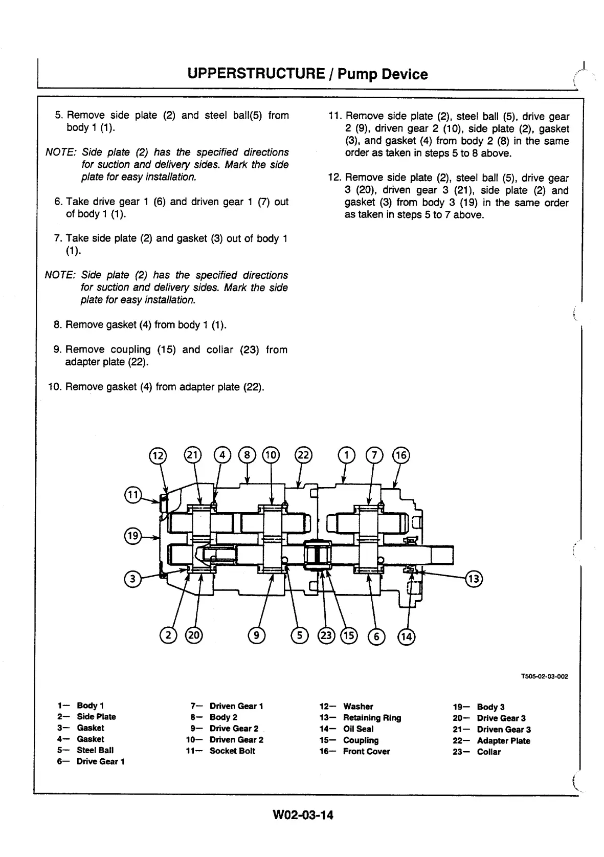
Remove side plate (2) and steel ball(5) from
body 1 (1).
NOTE: Side plate (2) has the specified directions
for suction and delivery sides. Mark the side
plate for easy installation.
6.
Take drive gear 1 (6) and driven gear 1 (7) out
of body 1 (1).
11. Remove side plate (2), steel ball (5), drive gear
2 (9), driven gear 2 (10), side plate (2), gasket
(3), and gasket (4) from body 2 (8) in the same
order as taken in steps 5 to 8 above.
12. Remove side plate (2), steel ball (5), drive gear
3 (20), driven gear 3 (21), side plate (2) and
gasket (3) from body 3 (19) in the same order
as taken in steps 5 to 7 above.
7.
Take side plate (2) and gasket (3) out of body 1
(1).
NOTE: Side plate (2) has the specified directions
for suction and delivery sides. Mark the side
plate for easy installation.
8.
Remove gasket (4) from body 1 (1).
9.
Remove coupling (15) and collar (23) from
adapter plate (22).
10.
Remove gasket (4) from adapter plate (22).
T505
,
02-03-002
1—
Body 1
7—
Driven Gear 1
12—
Washer
19—
Body 3
2—
Side Plate
8—
Body 2
13—
Retaining Ring
20—
Drive Gear 3
3—
Gasket
9—
Drive Gear 2
14—
Oil Seal
21—
Driven Gear 3
4—
Gasket
10—
Driven Gear 2
15—
Coupling
22—
Adapter Plate
5—
Steel Ball
11—
Socket Bolt
16—
Front Cover
23—
Collar
6—
Drive Gear 1
UPPERSTRUCTURE I Pump Device
W02-03-14



 To Next Page