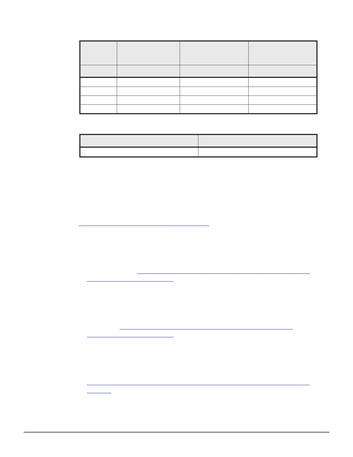
Table 9 Maximum cable length (shortwave)
Data
Transfer
Rate
OM2 cable (50/125 um
multi-mode fiber)
OM3 cable (50/125 um
laser optimizedmulti-
mode fiber)
OM4 cable (50/125 um
laser optimizedmulti-
mode fiber)
MB/s feet / meters feet / meters feet / meters
200 984.3 / 300 1640.4 / 500 -
400 492.1 / 150 1246.7 / 380 1312.4 / 400
800 164 / 50 492.1 / 150 623.4 / 190
1600 118 / 35 328 / 100 410.1 / 125
Table 10 Maximum cable length (longwave)
Data Transfer Rate ( MB/s)
Cable length (km) OM3 cable
200, 400, 800, 1600 10
Drive chassis
The VSP G1000 and G1500 support three different drive chassis. The VSP
F1500 only supports the FMD chassis. All components in the drive chassis are
configured with redundant pairs to prevent system failure. While the storage
system is in operation, all components in the drive chassis can be added or
replaced. For detailed information about the drives in each chassis, see
Storage system specifications on page 122.
• SFF - a 16U group of eight 2U drive trays. Each holds up to 24 vertically
positioned 2.5-inch HDD and SSD drives, for a total of 192 drives per
chassis. Each drive tray also contains two redundant power supplies, and
two ENC adapters that connect the drives to the controller. The connection
to the controller may be direct, or it can be connected through other SFF
drive trays. See
Figure 19 SAS Connection Diagram of Rack-00 (SFF/LFF
Standard Model) on page 94.
• LFF - a 16U group of eight 2U drive trays. Each holds up to 12 horizontally
positioned 3.5-inch drives, for a total of 96 drives per chassis. Each drive
tray also contains two redundant power supplies, and two adapters that
are used to connect the drives to the controller. The connection to the
controller may be direct, or it can be connected through other LFF drive
trays. See
Figure 19 SAS Connection Diagram of Rack-00 (SFF/LFF
Standard Model) on page 94.
• FMD - an 8U group comprising four 2U drive trays, each holds up to 12
horizontally mounted drives, with a total of 48 FMDs per chassis. Each
drive tray also contains two redundant power supplies and two adapters
that connects the drives to the controller. The connection to the controller
may be direct, or it can be connected through other FMD drive trays. See
Figure 21 SAS Connection Diagram of Rack-00 (FBX Standard Model) on
page 96.
Introduction 39
Hitachi Virtual Storage Platform G1000, G1500, and Virtual Storage Platform F1500 Hardware Guide
 Loading...