HTA-DD3
5
6
Claws (PWB Support)
5
6
Flat Cable
7
8
x 4
x 1
x 1
20
x 3
x 4
Z
19
E
A
B
C
D
F
H
I
J
K
N
L
M
O
P Q
Main PWB
DSP PWB
Push Rivet
Holder (Back)
Holder (Front)
Audio PWB
S Video PWB
Composit PWB
Component PWB
Relay PWB
Tuner
PWB
SHIELD
PLATE
DSP PWB
19
x 1
for E, E(BS)
Fig. 4
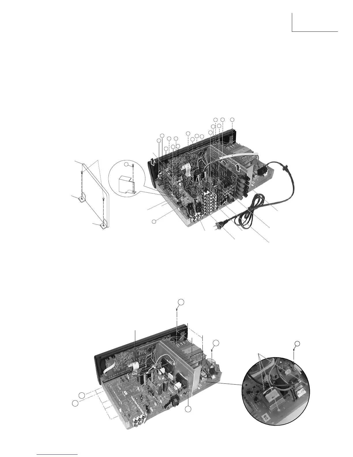
3. Removal of Tuner & DSP PWB board
(a) Remove the Push Rivet from the Holder (Front) & Holder (Back) then remove the flat cable Z at the Tuner PWB.
(b) Remove 1 screw + to detech the shield plate from the bottom chassis.
(c) Gently pull the Tuner & DSP PWB board upwards to detach its connectors A, B, C, D, E & F from Main
PWB board.
Removal of Audio PWB board
(a) Gently pull the Audio PWB board upwards to detach its 4 connectors H, I, J & K from Main PWB board.
Removal of S Video/Composit PWB board
(a) Gently pull the Composit and S Video PWB board upwards to detach its 2 connectors L & M from Main PWB
board.
Removal of Components PWB board
(a) Gently pull the Components PWB board upwards to detach its connector N from Main PWB board.
Removal of Relay PWB board
(a) Gently pull the Relay PWB board upwards to
detach its 3 connectors O, P & Q from
Main PWB board.
4. Removal of Transformer
(a) Remove 4 screws 5 from the transformer.
(b) Pull the transformer upward together with the Power PWB section.
Removal of Power PWB board
(a) Remove 1 screw 6 from the Botton chassis at the side.
(b) Release the Power PWB board from its 3 holding claws (PWB support) and gently pull the board free.
Removal of Main PWB board
(a) Detach Flat Cable from FL PWB Board.
(b) Remove 4 screws 7 to release the Power IC from the heat-sink.
(c) Remove 3 screws , to release the bracket from the heat-sink.
(d) Remove 1 screw 8 to release the Component from the heat-sink.
Removal of Heat-Sink
(a) Invert the Botton Chassis, remove 2 screws
9 connect to the heat-sink (Fig 5).
Fig. 3