EasyManua.ls Logo

Hitachi L-8900 User Manual

Hitachi L-8900
191 pages
To Next Page IconTo Next Page
Page #1 background imageLoading...
Page #1 background image
SERVICE MANUAL
FOR
L-8900 HIGH SPEED AMINO ACID ANALYZER
Hitachi High-Technologies Corporation
Copyright C Hitachi High-Technologies Corporation 2005.
All rights reserved. Printed in Japan. Part No. 852-9051 TR-F (HT-HMS056003)

Table of Contents

Question and Answer IconNeed help?

Do you have a question about the Hitachi L-8900 and is the answer not in the manual?

Hitachi L-8900 Specifications

General IconGeneral
ModelL-8900
CategoryAmino Acid Analyzer
Wavelength Range440 nm and 570 nm
Sample Volume20-100 μL
Data OutputDigital
Power SupplyAC 100-240 V, 50/60 Hz

Summary

PREFACE

ABOUT THIS MANUAL

IMPORTANT

CE Conformity Marking

Details on the instrument's compliance with European EMC and safety directives.

Precautions on Electromagnetic Disturbances

Electromagnetic Interference by This Instrument to the Surroundings

Guidance on managing interference caused by the instrument to nearby electronic equipment.

Electromagnetic Interference by the Surroundings to This Instrument

WARRANTY ON PRODUCT

Scope of Guarantee

Defines what is covered and not covered under the manufacturer's warranty.

Guarantee Period

Specifies the duration of the product warranty.

Items out of Guarantee

Lists conditions and circumstances excluded from the product warranty coverage.

INSTALLATION/RELOCATION

DISPOSAL

OTHER CAUTIONS

Handling Chemicals and Samples

Safety precautions for handling chemicals and samples used with the instrument.

SAFETY SUMMARY

General Safety Guidelines

Essential safety rules and practices to follow when operating the instrument.

WARNING Indications

Explanation of WARNING alerts and their meaning for potentially hazardous situations.

CAUTION Indications

Explanation of CAUTION alerts and their meaning for minor hazards.

SAFETY SUMMARY

General Safety Guidelines (Continued)

Continued essential safety rules and practices for instrument operation.

SAFETY SUMMARY

Precautions on Use

Specific safety measures and advice for using the instrument correctly and safely.

SAFETY SUMMARY

Precaution during Use

Immediate actions to take in case of abnormal conditions during instrument operation.

Precautions on Installation, Maintenance and Relocation

Safety guidelines for installing, maintaining, and relocating the instrument.

SAFETY SUMMARY

Safety Instructions in This Manual

Overview of safety instructions presented within the manual.

WARNING Indications (Continued)

Continuation of warnings about potentially hazardous situations.

SAFETY SUMMARY

WARNING Indications (Continued)

Continuation of warnings about potentially hazardous situations.

SAFETY SUMMARY

WARNING Indications (Continued)

Continuation of warnings about potentially hazardous situations.

SAFETY SUMMARY

WARNING Indications (Continued)

Continuation of warnings about potentially hazardous situations.

SAFETY SUMMARY

WARNING Indications (Continued)

Continuation of warnings about potentially hazardous situations.

SAFETY SUMMARY

CAUTION Indications

Explanation of CAUTION alerts and their meaning for minor hazards.

SAFETY SUMMARY

CAUTION

General cautionary advice for instrument operation.

SAFETY SUMMARY

When Stopping Instrument Manually

Procedures for manually stopping the instrument operation safely.

SAFETY SUMMARY

Starting Pump

Steps for starting the instrument pumps correctly after power-on or wake-up.

Data Backup

Importance and procedure for backing up instrument data regularly.

SAFETY SUMMARY

Warning Labels

Identification and explanation of various warning labels attached to the instrument.

3. TROUBLESHOOTING

3.1 Trouble Cause Analysis

Analysis of potential causes for common instrument troubles.

3.1.1 Pump Pressure Abnormal

Troubleshooting guide for abnormal pump pressure issues.

3.1.2 Baseline Noise

Troubleshooting guide for baseline noise occurring in chromatograms.

3.2 Remedies

Solutions and fixes for common instrument problems.

3.2.2 Pump

Solutions and fixes for common problems with the pump unit.

3.1.2 Baseline Noise

3.1.3 Baseline Drift

3.1.4 Poor Performance

3.2 TROUBLESHOOTING

3.2.1 Troubleshooting of Units (common)

Common troubleshooting steps for various instrument units and error messages.

3.2.2 Troubleshooting of Autosampler

3.2.2 Error messages (Autosampler)

3.2.3 Troubleshooting of Pump

3.2.4 Troubleshooting of Column Oven/Reaction Bath

3.2.5 Troubleshooting of N2 Gas Unit

3.2.6 Troubleshooting of 'Full Specifications' (option)

4. TECHNICAL INFORMATION

4.1 MAINTENANCE PARTS LIST

List of recommended maintenance parts with part numbers and expected life.

4.2 MAINTENANCE SPARE PARTS

List of essential spare parts to prepare for long-term instrument operation.

4.3 COLUMN REPLACEMENT

Guidelines and timing for replacing or repacking instrument columns.

4.4 L-8900 PART, PART NUMBER LIST

Comprehensive list of parts and their corresponding part numbers for the L-8900 model.

4.5 UNIT PARTS REPLACING PROCEDURE

Step-by-step procedures for replacing individual instrument unit parts.

4.5.1 Column Oven

4.5.2 Reaction Bath

4.5.3 Degasser

4.5.4 Pump Purge Valve

4.5.5 Weight Sensor

2. Weight sensor for C1

3. Adjustment specifications for 30N type Load Cell.

3a. Switching PC board switches

Configuration of PC board switches for load cell adjustments.

4.2.7 Adjustment Specifications for 100N type Load Cell

1. Switching PC board switches

Configuration of PC board switches for 100N type load cell adjustments.

4.6 ADJUSTING PC BOARD

4.6.1 Adjusting ZERO/SPAN of PUMP PC Board

Procedure for adjusting ZERO and SPAN on the pump PC board.

4.6.2 Adjusting Reaction Bath Device PC Board

Adjusting temperature for Oven

Procedure to adjust temperature settings for the oven component.

4.6.3 Adjusting Column Oven PC Board

Adjusting temperature for Oven

Procedure to adjust temperature settings for the column oven.

Adjusting temperature for room temperature

4.7 HANDLING UI PAD, BUTTON FUNCTION CORRESPONDENCE

4.7.1 Annex Board UI Pad Operation

Operation guide for the Annex Board UI Pad.

3. Monitor screen

4. SETUP process

4a. Setting OPTION Use/Unuse

Procedure to configure the instrument's option settings for use or non-use.

4b. Setting LCD contrast

5. Remaining volume sensor 0 point adjustment (ZERO ADJ)

6. UTILITY

6a. Setting Leak sensor

Procedure for configuring the leak sensor settings.

6b. Setting N2 gas auto purge time

6d. Setting Weight sensor correction factor

7. GLP Function

7a. VALVE1 Report

Procedure for generating Valve 1 reports and managing its settings.
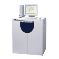
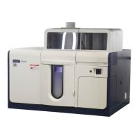
7b. VALVE2 Report

7c. Key-lock On/Off

8. Purge Valve1 switching

9. Option Valve 2 switching

10. N2 gas solenoid valve setting (GAS POS)

4.8 FLOW PATH DIAGRAM

4.9 Wiring Diagram between PC Boards

4.10 CIRCUIT DIAGRAM

Circuit Diagram of Oven RP PC Board

Module Circuit Table

Circuit Diagram of 1P1 Module

Circuit Diagram of IP2 Module

Circuit Diagram of AMP Module

Circuit Diagram of DC

Circuit Diagram of Lamp

Circuit Diagram of LOG

Circuit Diagram of N2 AMP

Circuit Diagram of OB2 Module

Circuit Diagram of OFF Module

Circuit Diagram of OFG Module

Circuit Diagram of OFH Module

Circuit Diagram of OK0 Module

Circuit Diagram of OK1 Module

Circuit Diagram of OKQ Module

Circuit Diagram of OKR Module

Circuit Diagram of OKS Module

Circuit Diagram of OP1 Module

Circuit Diagram of OR1 Module

Circuit Diagram of OT1

Circuit Diagram of OT2

Circuit Diagram of OT3

Circuit Diagram of OT4

Circuit Diagram of OT5

Circuit Diagram of OT6

Circuit Diagram of OT7

Circuit Diagram of OT8

Circuit Diagram of OTA

Circuit Diagram of OTB

Circuit Diagram of OTC

Circuit Diagram of OTD

Circuit Diagram of OTD_CO

Circuit Diagram of OTA_RA

Circuit Diagram of OTE

Circuit Diagram of OU7

Circuit Diagram of VALVE9

Related product manuals