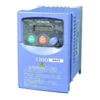
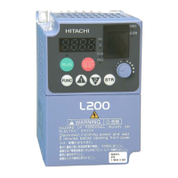
L100 Inverter
Index–3
Motor poles 1–14
Mounting dimensions 2–8
Mounting location 2–6
Multiple-motor operation 4–28
Multi-speed profile 1–11
Multi-speed select settings 4–7
Multi-speed setting 3–12
O
Operational modes 3–5
Optional components 2–5, 5–2
Orientation 2–2
Output deviation for PID loop 4–21
Output frequency 3–9
Output terminal functions 3–31, 4–18
Output wiring 2–16
Overload advance notice signal 4–20
Overload restriction setting 3–23
P
Parameter editing 2–19, 2–22
Parameter monitoring 2–24
Parameter settings
DOP Plus software B–7
keypad entry B–2
Parameters 2–20
PID loop 1–14
error deviation signal 4–21
operation 4–27
PID Loop settings 3–17
PLC connection 4–4
Potentiometer 2–23
Powerup test 2–17
observations 2–25
Programming
devices 3–2
read/write copy unit 3–5
Proportional gain 3–17
PTC thermistor thermal protection 4–17
Pulse-width modulation 4–25
PV source setting 3–17
R
Reduced torque 3–5, 3–13
Relay contacts 4–22
Reset function 4–16
Resistor
braking 5–5
Restart mode 3–21
Reverse run command 4–6
RF noise filter 5–4
Run command 4–6
Run signal 4–18
S
Single-phase power 1–13
Software lock function 4–14
Software lock mode 3–24
Spare parts 6–10
Specifications
by voltage class 1–4
control and logic connections 4–5
general 1–6
label 1–3, 2–3
Standard functions 3–10
Step-up transformer 1–13
System description 2–5
System diagram 5–2
T
Terminal tightening torque 2–15
Thermal overload setting 3–22
Thermistor thermal protection 4–17
Three-phase power 1–9, 1–13
Torque 1–8
Torque boost 3–13
Trip event 3–9
external 4–12
Trip events 6–5
Trip mode 4–16, 4–22
Troubleshooting Tips 6–3
Two-stage acceleration and deceleration 4–10
 Loading...
