30
Stem
Baffle
Cover
Screw (4 pcs)
Diaphragm
Valve
Regulator
O-ring
Filter element
IN
OUT
Nut A
Fig. B
Nut
Plate
Spring
Valve seat
Locked joint
Pull
Fig. A
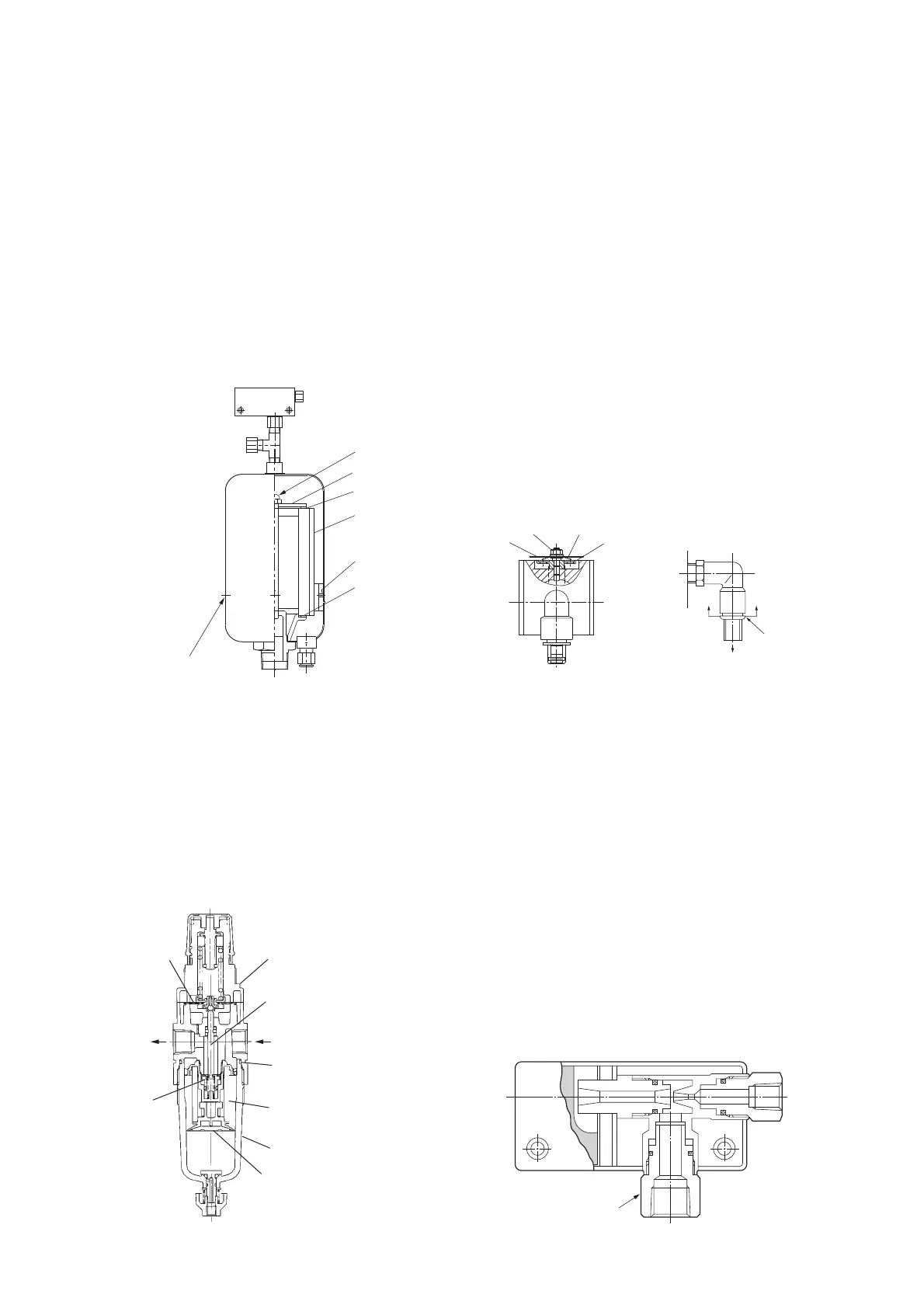
1. Replacement of remover element
① Remove the pipe provided at the top of the remover
if required. Then remove 4 set screws (A) from the
oil mist remover housing.
Pull up the upper part of the housing.
② Loosen nut (B) and remove the cover. Now you can
remove the remover element.
③ Install a new element. Carefully seat the upper and
lower rubber gaskets on the element without
allowing any gaps.
④ After replacement
of element, grease
the O-ring, replace
the housing, and
tighten set screws
(A) diagonally and
evenly.
2. Maintenance of Filter Regulator
① Turn the cover to remove. Remove the baffle and
replace the filter element with a new one.
② Remove the upper 4 set screws and remove the
upper part of the regulator. Replace the diaphragm
and the valve stem with new components. Be careful
not to install the new diaphragm upside down.
3. Maintenance of Relief Valve (See Fig. A.)
① Turn the nut at the top of the relief valve and remove
the plate. Replace the sheet and the spring with new
components.
② Ensure that the spring is positioned at the center
before assembly.
4. Maintenance of Vacuum Indicator (See Fig. B.)
① Contamination of the vacuum indicator may cause
malfunction of indicator.
Remove and clean the indicator at least every six
months. In addition, replace the indicator once a year.
② Pull down the indicator while pushing up the locked
pipe joint at the top.
5. Maintenance of Ejector
① If the ejector is dirty, performance may decrease.
Disassemble and clean at least once a year.
② The maintenance procedure is as follows:
(1) Disconnect the control air tube at its detachable
connection.
(2) Loosen nut A (the nut can be turned
independently from the ejector body) and
disconnect the ejector from the manifold.
(3) Remove the plastic case.
(4) Clean the ejector body with a neutral detergent
and dry it with an air nozzle. Assemble all of the
parts.
4.12 Maintenance of Oil Mist Remover
3/8
φ12
(B)
Rubber packing
Rubber packing
O-ring
Remover
element
Cover
(A)

 Loading...