APPENDIX - 3
(1) Contact Signal Input Terminals
These are contact signal input terminals for control using
contact signals from an external switch, relay etc.
Shorting the terminal for 0.1 second or longer activates any
of the signals. The input circuit is shown in Figure A-3.
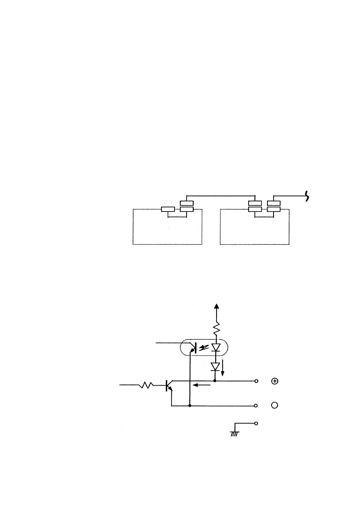
(2) Contact Signal Output Terminals
These are contact signal output terminals for control using
contact signals of an external unit. The output circuit is
shown in Fig. A-4. The rating of contacts used is 12 V,
0.1 A. Make sure the load connected does not exceed this
rating.
Fig. A-1 e-Line Cable Connection
Fig. A-2 e-Line Contact Circuit Configuration