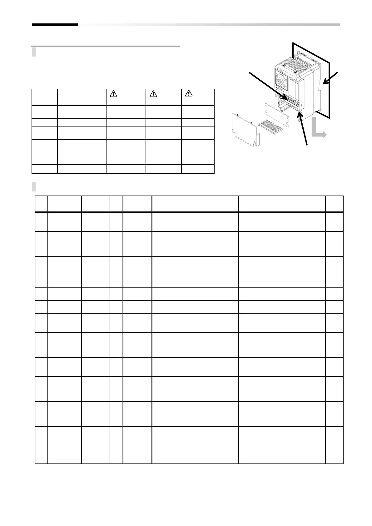
2.12 Residual risk
Parts subject to residual risk
Please check for any residual risk upon completion of the
installation before power on.
■Residual risk checklist No.
Residual risk checklist
Installation, wiring, and setting work need to be performed by
specialized technicians.
(*1)SH1-00041-H~SH1-00620-H (SH1-007H~SH1-220H)
(*2)SH1-00770-H~SH1-06600-H (SH1-300H~SH1-3150H)
Main circuit terminal
block
Input/output
terminal block
Motor connected
with the inverter
and wiring to the
motor
Details of harm or damage
Damage caused by careless transport
Do not drop the product. Do not carry the
inverter in a manner that applies force to
the cover or operator keypad.
Reduction of component life due to use in
a location exposed to direct sunlight or at
a temperature outside the specification
range.
Check that ambient temperature is within
the standard specification range in the
whole year by means of cooling and
ventilation.
Failure due to short circuit caused by
using in a location which humidity and
condensation are out of standard range
described in specification.
Check that ambient temperature is within
the standard specification range in the
whole year by means of cooling and
ventilation. Otherwise, install the product
in a location free from condensation.
The cooling fin that is heated to exceed
150°C catches fire to a flammable wall.
Install the inverter on an inflammable
metal wall.
Component failure due to entry of dust,
corrosive gas, or other substances.
Install the inverter inside a totally
enclosed panel.
Reduction of a component life due to
degradation of cooling capability by
horizontal installation.
Install the inverter vertically.
When the fin of the inverter is installed
outside of cabinet, the cooling fan fails
due to droplet, oil mist, etc.
When installing the fin of inverter outside
the cabinet, install it in a location free
from droplet, oil mist, etc.
Maintenance
for installation
The arc flies due to screws loosened by
vibration, and catches fire to the internal
components.
Check screws are appropriately tightened
on a regular basis.
Maintenance
for installation
The arc flies due to screws loosened by
vibration, and catches fire to the internal
components.
Check screws are appropriately tightened
on a regular basis. Do not place
flammable materials near the installed
inverter.
When the cover is removed, electric
shock is caused in a high-voltage section.
Do not remove the cover when power is
supplied.
After power is turned off, wait 10 minutes
or more to perform working.
When the operator removes the cover,
electric shock is caused when a tool
touches a high-voltage section.
Do not open the cover when the power is
on. Wait for 10(*1)/15 (*2) minutes or
more after the power is off, and then
confirm that the voltage between P and N
is significantly less than 45Vdc to start the
work.
(B)
(B)
(B)
(B)
(B)
(B)
(B)
(B)
(B)
(B)
(B)
(B)
(B)
(B)
(B)
(B)
(A)
(A)
(A)
(A)
(A)
(A)
(A)
(A)
(A)
(A)
(A)
(A)
(A)
(A)
(A)
(A)
(C)
(C)
(C)
(C)
(C)
(C)
(C)
(C)
(C)
(C)
(C)
(C)
(C)
(C)
(C)
(C)
Motor and
wiring to the motor
 Loading...


