SJ100 Inverter
Operations
and Monitoring
4–11
Set Second Motor
If you assign the [SET] function to a logic terminal, the inverter will display the x2xx
numbered parameters, allowing you to edit the second motor parameters. These parame-
ters store an alternate set of motor characteristic parameters. When the terminal [SET] is
turned On, the inverter will use the second set of parameters to generate the frequency
output to the motor. When changing the state of the [SET] input terminal, first confirm
the inverter is in the Stop Mode, and the motor is not rotating.
When the switch between the set terminals [SET] and [P24] is on, the inverter operates
per the second set of parameters. When the terminal is turned off, the output function
returns to the original settings (first set of motor parameters). Refer to the section on
two-motor operation on page 4–34 for details.
Option
Code
Terminal
Symbol
Function Name
Input
State
Description
08 SET Set 2nd Motor ON causes the inverter to use the 2nd set of motor
parameters for generating the frequency output
to motor
OFF causes the inverter to use the 1st (main) set of
motor parameters for generating the frequency
output to motor
Valid for inputs:
C01, C02, C03, C04, C05, C06
Required settings:
(none)
Notes:
•
If the terminal is turned off while the motor is
running, the inverter continues to generate the
frequency output using the 2nd set of parameters
until the motor is stopped.
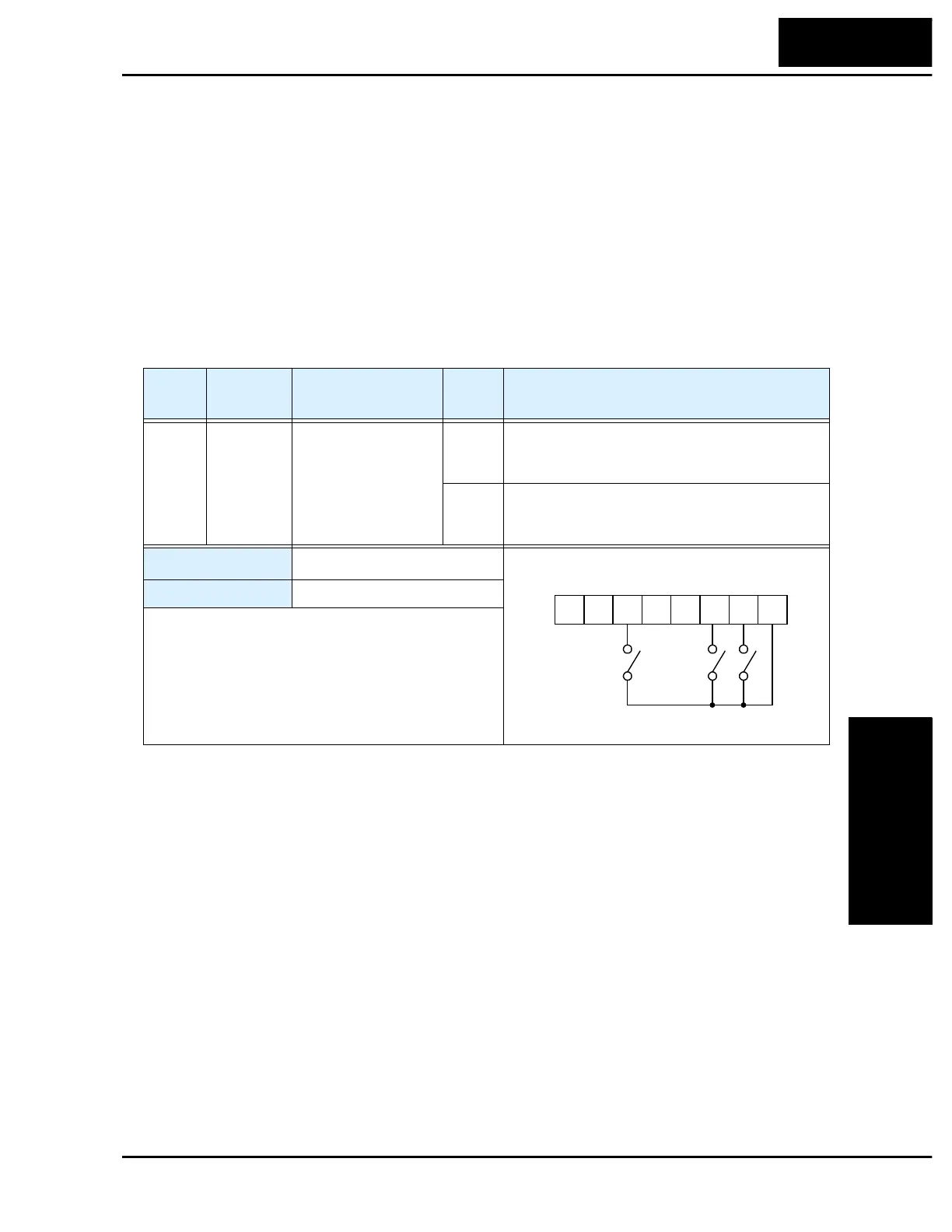
P24
1236 45L
Example:
FW
SET
RV
See I/O specs on page 4–5.

 Loading...


