Using Intelligent Input Terminals
Operations
and Monitoring
4–20
Remote Control Up and Down Functions
The [UP] [DWN] terminal functions can adjust the output frequency for remote control
while the motor is running. The acceleration time and deceleration time of this function
is same as normal operation ACC1 and DEC1 (2ACC1,2DEC1). The input terminals
operate according to these principles:
• Acceleration - When the [UP] contact is turned On, the output frequency accelerates
from the current value. When it is turned Off, the output frequency maintains its
current value at that moment.
• Deceleration - When the [DWN] contact is turned On, the output frequency deceler-
ates from the current value. When it is turned Off, the output frequency maintains its
current value at that moment.
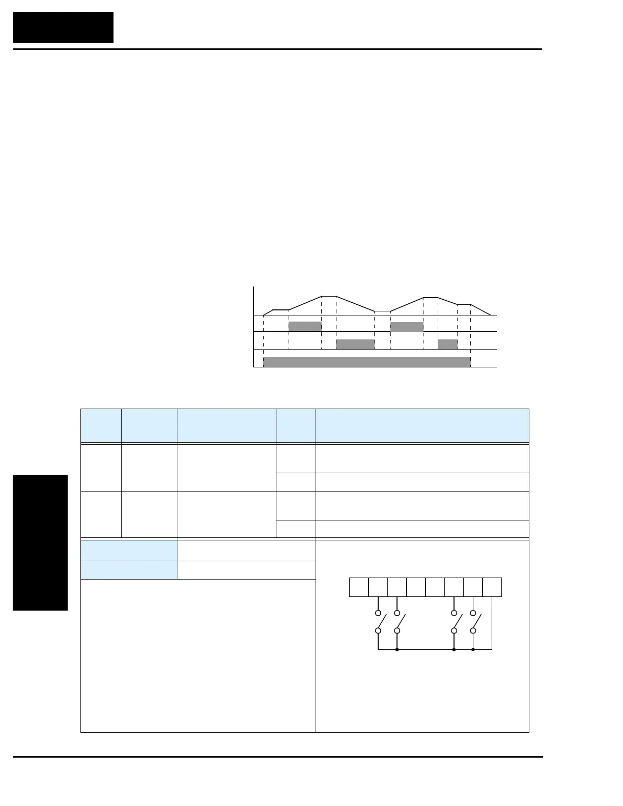
In the graph below, the [UP] and [DWN] terminals activate while the Run command
remains On. The output frequency responds to the [UP] and [DWN] commands.
time
Inverter output frequency
[UP] terminal
RUN command [FW, RV]
[DWN] terminal
Option
Code
Terminal
Symbol
Function Name
Input
State
Description
27 UP Remote Control
UP Function
ON Accelerates (increases output frequency) motor
from current frequency
OFF Output to motor operates normally
28 DWN Remote Control
DOWN Function
ON Decelerates (decreases output frequency) motor
from current frequency
OFF Output to motor operates normally
Valid for inputs:
C01, C02, C03, C04, C05, C06
Required settings:
A01 = 02
Notes:
•
This feature is available only when the frequency
command source is programmed for operator
control. Confirm A01 is set to 02.
•
This function is not available when [JG] is in use.
•
The range of output frequency is 0 Hz to the value
in A04 (maximum frequency setting).
•
The minimum ON time of [UP] and [DWN] is
50 ms.
•
This setting modifies the inverter speed from using
F01 output frequency setting as a starting point.
P24
1236 45L
Example:
FW
RV
DWN UP
See I/O specs on page 4–5.

 Loading...


