Auto-tuning for Sensorless Vector Control
Operations
and Monitoring
4–32
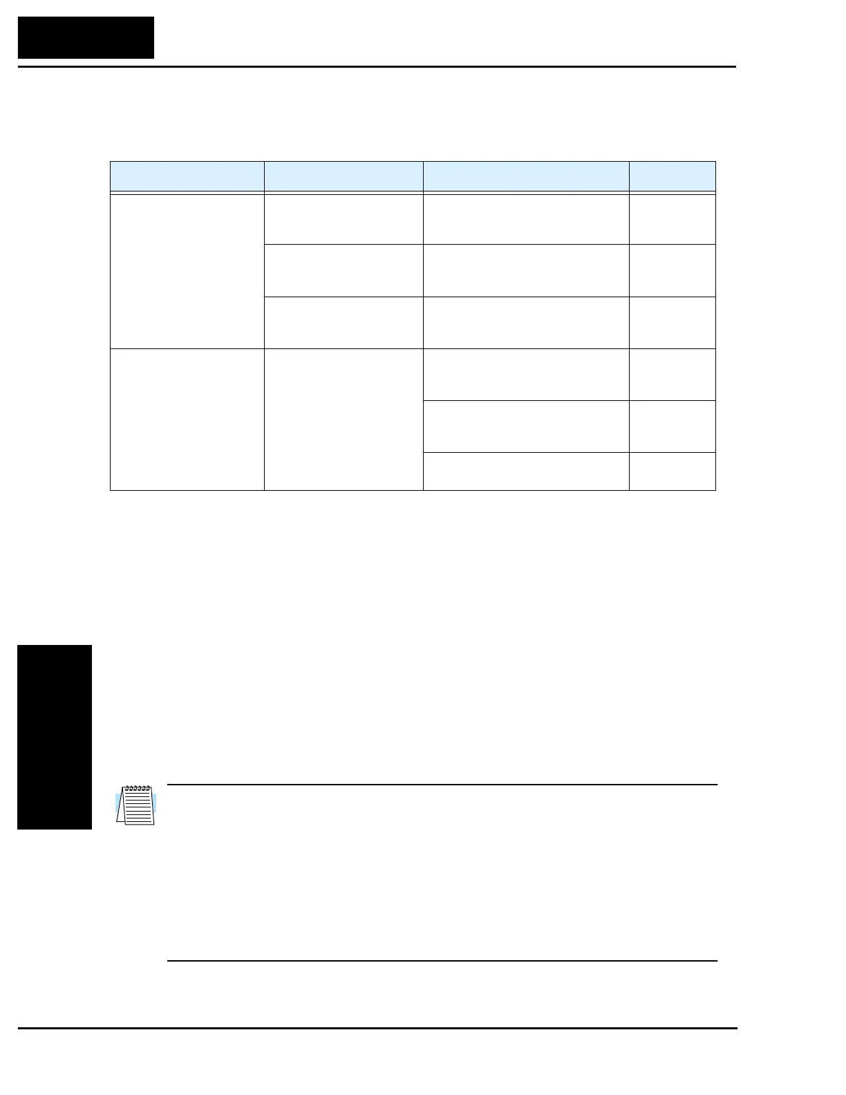
If the desired characteristic cannot be obtained in sensorless vector controlled operation
with standard (factory default) or auto-tuning data, adjust the motor constant(s)
according to the observed symptoms shown below.
Note 1:
If the inverter is using sensorless vector control and the motor is more than one frame size
smaller than the maximum applicable motor, then the motor characteristic values may not be
satisfactory.
Note 2:
No sensorless vector control operation is possible if two or more motors are connected (parallel
operation).
Note 3:
When the auto-tuning function is executed in the state that the DC braking is set, the motor
constants will not be accurately set. Therefore, disable DC braking and then start the auto-
tuning procedure again.
Note 4:
When accelerating or speeding up is not to be performed in the auto-tuning step for accelerating
up to 80% of the base frequency, lower the set value of manual torque boost.
Note 5:
Be sure the motor is stopped before you carry out an auto-tuning procedure. Auto-tuning data
which is derived while the motor is still running may not be correct.
Note 6:
Do not interrupt an auto-tuning procedure by removing power or by using the Stop command,
unless it is emergency. If this does occur, initialize the inverter’s parameters to the factory
default settings (see page 6–8). Then reprogram the parameters unique to your application, and
initiate the auto-tuning procedure again.
NOTE:
When the data of the H Group parameters does not match that of the motor,
satisfactory characteristics may not be obtained during sensorless vector operation. Also,
the stabilization adjustment (H06) is effective for V/F settings (00 and 01). The full
performance may not be achieved if the rating of a motor used is more than one frame
size smaller than the maximum applicable rating when the sensorless vector function is
used. You must disable sensorless vector operation when two or more motors are
connected. For the motor stabilization, set this data properly for the H03 (H203) param-
eter according to the motor used if its rating is not the same as the maximum applicable
rating in V/F operation.
Operation Status Symptom Adjustment Parameter
Powered running
(status with an accelerating
torque)
When low frequency (a few
Hz) torque is insufficient
Increase the motor speed constant R1
in relation to auto-tuning data, step by
step, within 1 to 1.2 times R2.
H20 / H30 /
H220/ H230
When the speed fluctuation
coefficient becomes
negative
Increase the motor constant R2 in
relation to auto-tuning data, step by
step, within 1 to 1.2 times R2.
H21 / H32 /
H221 / H231
When the speed fluctuation
coefficient becomes positive
Decrease the motor constant R2 in
relation to auto-tuning data, step by
step, within 0.8 to 1 times R2.
H21 / H32 /
H221 / H231
Regeneration
(status with a decelerating
torque)
When low frequency (a few
Hz) torque is insufficient
Increase the motor speed constant R1
in relation to auto-tuning data, step by
step, within 1 to 1.2 times R1.
H20 / H30 /
H220/ H230
Increase the motor constant R2 in
relation to auto-tuning data, step by
step, within 1 to 1.2 times R2.
H21 / H32 /
H221 / H231
Decrease the carrier frequency set
value.
B83

 Loading...


