SJ100 Inverter
Motor Control
Accessories
5–5
Dynamic Braking
The purpose of dynamic braking is to improve the ability of the
inverter to stop (decelerate) the motor and load. This becomes neces-
sary when an application has some or all of the following factors:
• High load inertia compared to the available motor torque
• The application requires frequent or sudden changes in speed
• System losses are not great enough to slow the motor as needed
When the inverter slows its output frequency to decelerate the load,
the motor can temporarily become a generator. This occurs when the
motor rotation develops a voltage higher than the inverter internal
(DC) bus voltage. This condition can cause the inverter to have an
over-voltage fault and enter the Trip Mode. In many applications, the
over-voltage condition serves as a warning signal that we have
exceeded the deceleration capabilities of the system. The SJ100
inverter has a built-in braking unit, which sends the excess energy
from the motor during deceleration to the braking resistor(s). The
power resistor serves as a generator load, developing heat to stop the
motor just as brakes on an automobile develop heat during braking.
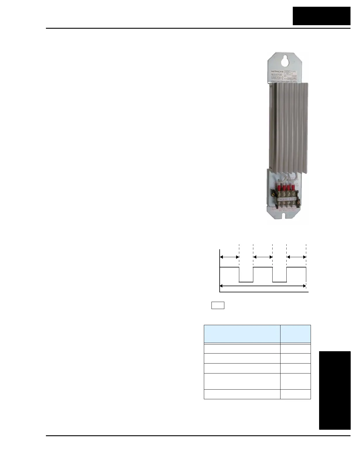
The braking resistor is the main component of a braking resistor
assembly, which includes a fuse and thermally activated alarm relay
for safety. However, be careful to avoid overheating its resistor. The
fuse and thermal relay are safeguards for extreme conditions, but the
inverter can maintain braking usage in a safe zone.
The inverter’s method uses the duty cycle, or
percent of the time braking is on versus total
time. Parameter B90 sets the dynamic braking
usage ratio. In the graph to the right, the
example shows three uses of dynamic braking
in a 100-second period. The inverter calculates
the average percentage usage in that time
(T%). The percentage of usage is proportional
to the heat dissipated. If T% is greater than the
B90 parameter setting, the inverter enters the
Trip Mode and turns off the frequency output.
Please note the following:
• When B90 is set for 0%, dynamic braking is
not performed.
• When the T% value exceeds the limit set by
B90, dynamic braking is terminated.
• When mounting an external dynamic
braking unit, set the usage ratio (B90) to 0.0
and remove the external resistors.
• The cable from the external resistor to the inverter must not exceed 5 m (16 ft.) length.
• The individual wires from the resistor to the inverter must not be bundled together.
Braking
Resistor
ON
B90
time
BRD
t1
T%
t1 t2 t3++()
100 seconds
-------------------------------
100×=
t2
t3
OFF
Inverter models
Minimum
Resistance
055L, 075L 17
Ω
007N, 011N, 015N, 022N, 040L 35
Ω
055H, 075H 70
Ω
002N, 004N, 022H, 030H,
040H, 055H, 075H
100
Ω
004H, 007H, 015H 180
Ω
Braking Resistor Table

 Loading...


