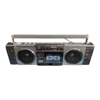
This document is a service manual for the HITACHI TRK-6701W, a cassette tape recorder with FM/SW/MW radio, manufactured by TOKAI WORKS in December 1982.
Function Description
The HITACHI TRK-6701W is a portable audio device designed for both recording and playback of cassette tapes, as well as receiving radio broadcasts across multiple bands. It integrates a cassette tape mechanism with a multi-band radio tuner (FM, SW, MW) into a single unit, offering versatility for personal entertainment and recording needs. The device features various controls for mixing volume, function selection (radio/tape), mode selection (play, record, fast forward, rewind, stop, eject, pause), tape selection (normal/chrome/metal), and tone adjustments (treble, bass). It also includes a loudness switch and a mono/stereo indicator for FM radio. For recording, it supports both built-in microphone and external microphone inputs, and features a record level control.
Important Technical Specifications
General Section
- Semiconductors: IC's: 8, Transistors: 8, Diodes: 10, LEDs: 10.
- Power (Mains) Supply: AC: 110/220V, 50/60 Hz (using accessory AC adaptor) or DC: 9V (UM-1 Cell x 6 or equivalent).
- Power Output: 2.5W/CH (T.H.D. 10%), 15W M.P.O. (AC operation).
- Speakers: 10 cm, 2.8 ohms x 2; 4 cm, 4.0 ohms x 2.
- Dimensions: 511(W) x 284(H) x 107.5(D) mm.
- Weight: 3.0 kg (with batteries).
Radio Section
- Circuit System: FM/SW/MW 3-band superheterodyne.
- Tuning Range: FM: 88 to 108 MHz, SW: 3.2 to 12 MHz, MW: 530 to 1605 kHz.
- Sensitivity: FM: 10 dB (S/N), 35 dB (max.), SW: 35 dB (S/N), 35 dB (max.), MW: 40 dB (S/N), 35 dB (max.).
- Intermediate Frequency: FM: 10.7 MHz, SW/MW: 455 kHz.
- Antennas: FM/SW: Telescopic antenna, SW/MW: Built-in ferrite-core antenna.
Tape Recorder Section
- Tape: Cassette tape (C-30, 60, 90).
- Tape Speed: 4.75 cm/s.
- Track System: 4 track 2 channel.
- Recording System: AC bias, 87 kHz.
- Erasing System: AC erase.
- Frequency Response: NORMAL: 50 to 14,000 Hz, CrO2: 50 to 12,000 Hz, METAL: 50 to 10,000 Hz.
- S/N (Signal to Noise Ratio): 45 dB.
- Wow and Flutter: 0.15% (WRMS).
- Cross Talk: 60 dB (Between tracks), 40 dB (Between channels).
- Erase Ratio: 70 dB.
- Input Sensitivity and Impedance: MIX. MIC.: 1.5 mV, 10k ohms; LINE IN: 400 mV, 100k ohms.
- Output Level and Impedance: LINE OUT: 700 mV, 5k ohms; Headphones: 8-32k ohms.
- Fast Forwarding or Rewinding Time: 120 sec. (Using C-60).
- Distortion: 4%.
- Motor: DC micromotor.
Usage Features
The TRK-6701W offers a user-friendly interface with clearly labeled controls.
- Cassette Loading: To load a cassette, the user presses the eject button to open the cassette lid, slides the cassette in the direction of the arrow, and pushes the cassette lid closed. For proper insertion, the front of the cassette is inserted into the recess of the front case and pushed into the mechanism.
- Radio Tuning: A dial pointer and tuning knob allow for precise selection of radio stations across FM, SW, and MW bands.
- Tape Operation: Dedicated buttons for Play, Record, Fast Forward, Rewind, Stop, Eject, and Pause provide full control over tape functions.
- Audio Adjustment: Separate controls for volume, bass, treble, and loudness allow users to customize the audio output to their preference.
- Recording: The device supports recording from its built-in microphone or an external microphone, with a record level control to adjust input sensitivity.
- Portability: The option to operate on DC power (6 UM-1 batteries) makes the TRK-6701W portable for outdoor use.
Maintenance Features
The service manual provides detailed instructions for disassembly, inspection, lubrication, and adjustment, ensuring the longevity and optimal performance of the device.
- Safety Precautions: Emphasizes the importance of following precautions to prevent electric shock and ensure safety during servicing. It advises using a suitable isolation transformer and checking for proper insulation resistance after repairs.
- Disassembly: Step-by-step instructions are provided for disassembling various components, including the cassette lid, rear case, radio PC board, indicator PC board, cassette chassis, and tape/audio PC board. This includes details on which screws to remove and how to detach connectors and springs.
- Inspection of Mechanism: A comprehensive table outlines check items, reference values, and remarks for inspecting the tape mechanism. This includes pressure of pressure roller, torque (take-up, fast forward, rewind), supply side, back tension, brake torque, button operation force (playback, fast forward, rewind, stop, record, pause), and flywheel thrust gap. These checks ensure the tape transport system operates within specifications.
- Lubrications: Specifies lubrication points for rotating parts and lubricate grease sliding points. It recommends using one or two drops of oil (Pan motor oil 10W-40, Solid slider oil E-1600, Hitsol MO-138) for metal-to-metal and mold-to-mold sections, and white grease (FL-LUBE-A) or Floil (GB-TS-1) for sliding sections and spring resonance prevention. Regular lubrication every 1,000 hours of operation or once a year is recommended to prevent irregular splashes.
- Adjustments:
- Radio Section: Detailed steps for adjusting FM IF, FM S-curve, FM OSC, FM MPX, FM MIX, FM MPX, SW OSC, MW OSC, SW ANT, and MW ANT. These adjustments involve using specific test equipment (e.g., signal generator, oscilloscope, VTVM) and tuning to specific frequencies to ensure accurate reception and performance.
- Tape Recorder Section: Instructions for adjusting tape speed and head azimuth. Tape speed adjustment involves playing a test tape and adjusting the motor speed until the frequency is within tolerance. Head azimuth adjustment ensures optimal playback quality by aligning the playback head with the tape tracks.
- Dial Cord Stringing: A diagram and step-by-step method are provided for correctly stringing the dial cord, which is crucial for accurate radio tuning.
- Replacement Parts List: Extensive lists of replacement parts, including mechanical components, miscellaneous parts, capacitors, resistors, semiconductors, filters, coils, and accessories, are provided with their symbol numbers and descriptions to facilitate repairs.
- Schematic Diagrams and Circuit Board Diagrams: Detailed schematic diagrams for the radio section and tape recorder section, along with circuit board diagrams, are included to aid in troubleshooting and component identification. These diagrams show the layout of components and their interconnections.
- Wiring Diagram: A wiring diagram illustrates the connections between different modules and components within the device, such as the indicator, built-in mic, speakers, battery case, and motor.