--- 11 ---
(3) Disassembly of the power supply unit
1) Removal of the Controller Circuit [95] (Fig. 10)
Remove the rubber bushing and pull out the cable of the Controller Circuit [95] from the Gear Cover Ass'y
[22]. Disconnect the cable connector from the cable and separate the Controller Circuit [95] from the Gear
Cover Ass'y [22]. (The cable connector can be disconnected by pulling it out with hands.) Disconnect the
Connector [98] which connects the seven internal wires with the Stator Ass'y [88].
2) Disassembly of the housing
Remove the Brush Cap [76] and take out the Carbon Brush [77]. Remove the four Hex. Socket Hd. Bolts
(W/Flange) M5 x 30 [79] from the Housing Ass'y [86]. The Housing Ass'y [86] can then be removed from
the Inner Cover Ass'y [13].
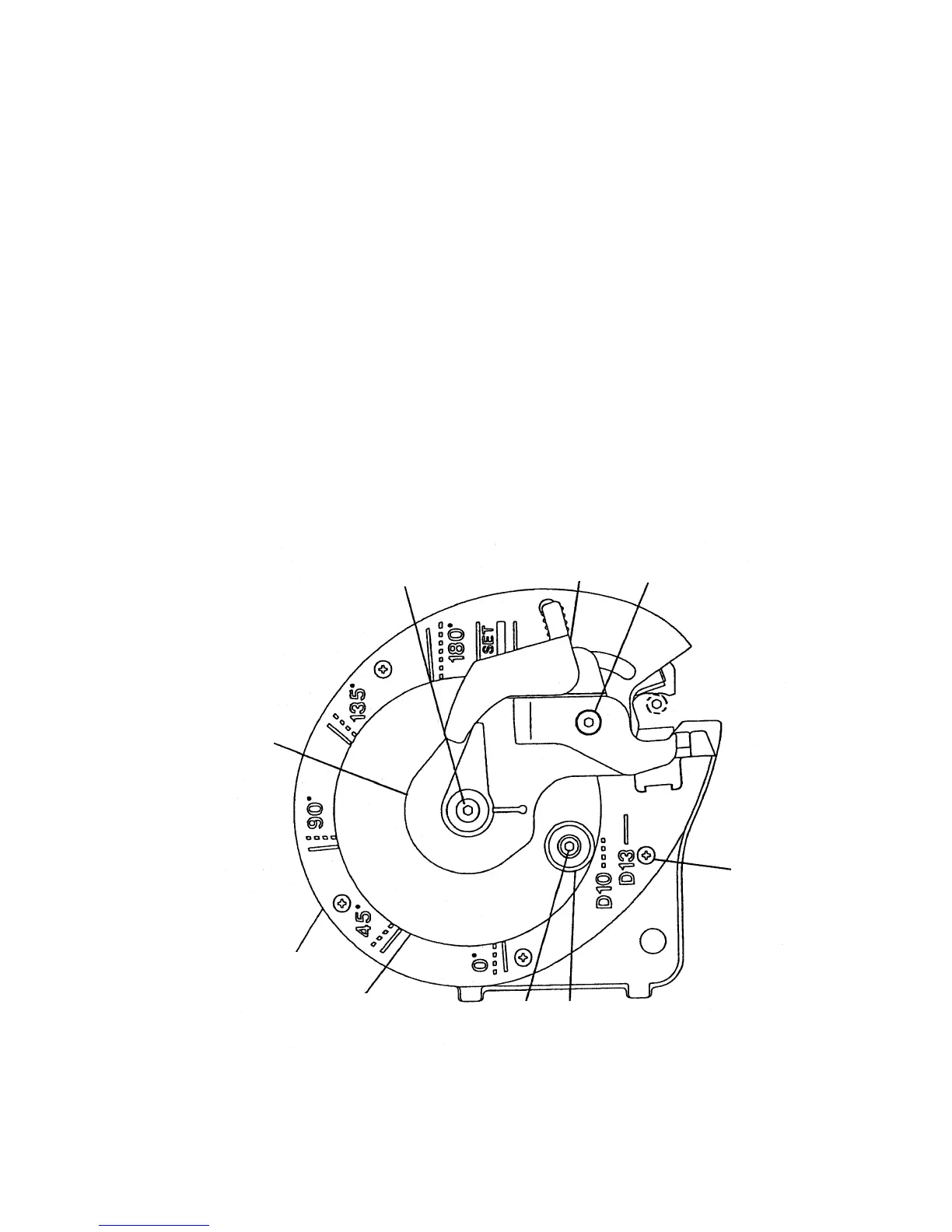
(4) Disassembly of the bending unit (Fig. 12)
1) Remove the Hex. Socket Hd. Bolt M5 x 12 [1], Hex. Socket Hd. Bolt (W/Flange) M5 x 16 [29] and the
Center Plate (A) [3].
2) Remove the Hex. Socket Hd. Bolt M5 x 12 [1] and the Roller (B) [30].
3) Remove the Lever (A) [31], Turn Table [5] and the five Flat Hd. Screws M4 x 10 [32] to remove the Cam
Cover [6].
Fig. 12
[1]
[31]
[29]
[3]
[6]
[5]
[32]
[30]
[1]