--- 10 ---
12. PRECAUTIONS IN DISASSEMBLY AND REASSEMBLY
The [Bold] numbers in the descriptions below correspond to the item numbers in the Parts List and exploded
assembly diagram.
12-1. Disassembly
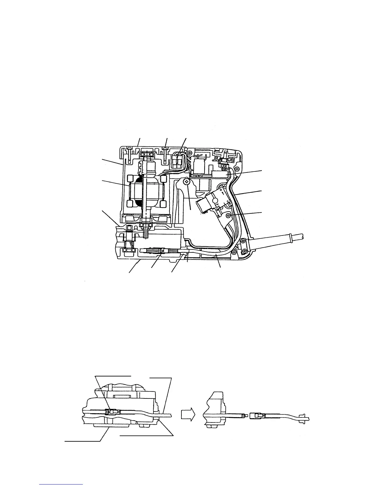
(1) Disassembly of the handle (Fig. 10)
Remove the two Tapping Screws (W/Flange) D4 x 20 [81] and the Tail Cover [82]. Remove the two Tapping
Screws (W/Flange) D5 x 20 [104], four Tapping Screws D4 x 20 (W/Flange) [81] and two Machine Screws
(W/Washers) M5 x 20 [105] to remove the Handle (A).(B) Set [94].
(2) Removal of the cable (Fig. 11)
Disconnect the connector by pulling the rubber bushing and the cable in the direction of the arrow.
*1. Gently pull the cable by moving it from side to side to disconnect the connector.
*2. If the one part of the connector remains in the gear cover due to yanking the cable, disassemble the gear
cover referring to "(5) Disassembly of the gear" and remove the remaining connector from the gear cover.
Fig. 10
Connector
Cable
Rubber bushing
Fig. 11
Gear cover
CableCable
connector
Rubber
bushing
[82] [81]
[98]
[95]
[81]
[86]
[88]
[13]
[22]
[105]
[104]
[94]