--- 19 ---
12-5. Repair Procedure
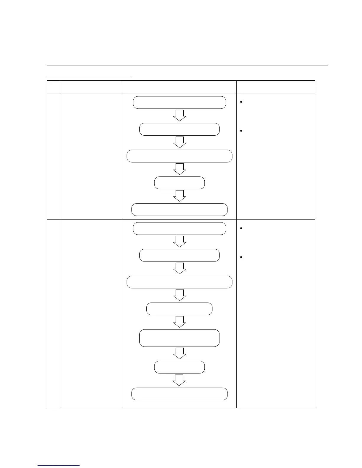
Following table shows rough repair procedures. Refer to the above mentioned disassembly and reassembly
procedures for details.
* Be sure to confirm the operation of the controller circuit, gears, brackets and cam after reassembly of them, and
perform adjustment if necessary.
No. Item Procedure Remarks
Replacement of
control circuit
1
12-1 (1) Disassembly of the handle
12-1 (2) Removal of the cable
12-1 (3) Disassembly of the power supply unit
12-2 Reassembly
12-4 Confirmation after Reassembly
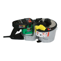
12-1 (1) Disassembly of the handle
12-1 (4) Disassembly of the bending unit (Fig. 12)
12-1 (2) Removal of the cable
Removal of sensor gear
Disassembly of the gear unit,
bracket unit and cam unit
12-2 Reassembly
12-4 Confirmation after Reassembly
Replacement of gears,
brackets and cam
2
Wiring of the controller
circuit
* Refer to "12-3. Wiring
Diagram".
Confirmation after reas-
sembly
* Refer to 12-4 (1) and (2).
Removal and installation of
the sensor gear
* Refer to 12-1 (5) and 12-2
(6).
Confirmation after reas-
sembly
* Refer to 12-4 (1) and (2).