[1] Overview
This engineering note applies when using SLV , 0-SLV and V2 (closed loop) control. It is often difficult to
get optimized motor performance because many parameters interact. Please refer to this document for
getting a rough idea how to achieve good motor performance with above control modes. Please also note that
the performance WILL NOT BE like a servo drive even in the case of V2 mode.
There are 3 basic modes with which you can get high torque performance with the SJ300 inverter:
(1) SLV control (No SJ-FB is used)
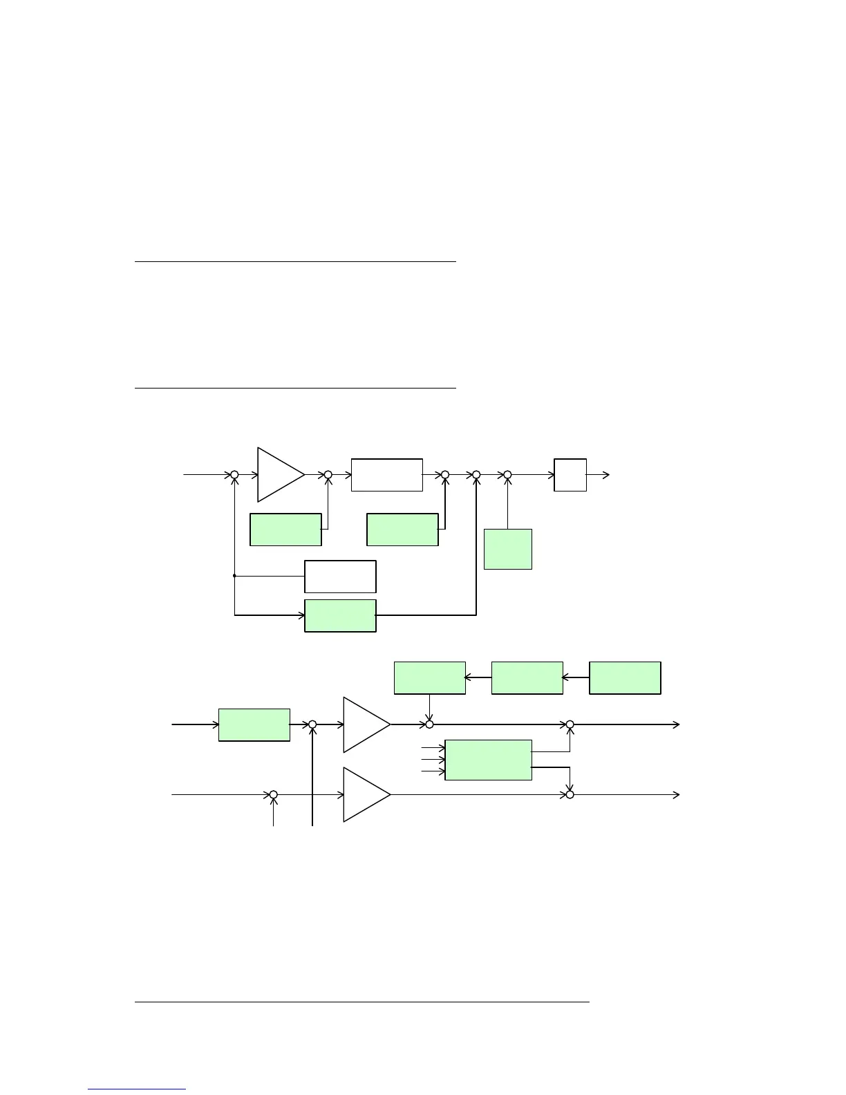
High motor torque performance with open loop can be obtained in the low frequency range (~0.5Hz).
Please refer to a standard SLV block diagram in Fig 1 (section 2-2).
[H***] parameters are mainly adjusted for the control.
(2) 0-SLV control (No SJ-FB is used)
High torque performance can be obtained at around 0Hz. This does NOT mean the motor shaft will be at a
standstill. The motor rotates slightly to generate motor torque, since this is not a servo drive. Depending on the
application and tuning, you may be able to get full torque with the motor at standstill. This control algorithm is
different from SLV control.
[H***] parameters are mainly adjusted for the control.
ΠFrequency control block portion
• Voltage control block portion
(3) V2 control (SJ-FB is used)
High torque and stable, accurate motor performance can be achieved with the SJ300 in vector mode.
A motor encoder and a feedback option card for SJ300 (SJ-FB) are needed to use this control mode.
There are two regulation modes within the V2 control mode: ASR mode and APR mode .
ΠASR mode : Inverter is controlled by speed command input (digitally set, analog input, or RS485)
• APR mode : Inverter is controlled by pulse train input signal
[H***] and [P***] parameters are adjusted for achieving good motor control.
A suitable mode should be selected depending on the application.
 Loading...


