47
Competition Glider Quick Setup Instructions
edge should raise no more than 1/16” (1.5 mm), or you’ll
gain more drag than penetration ability.
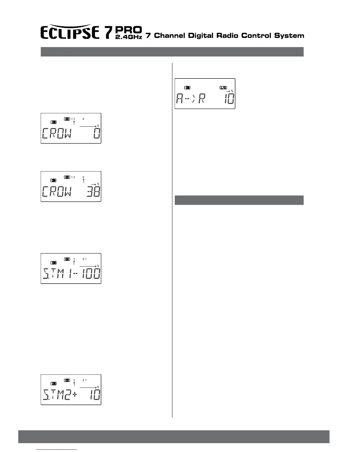
31. If desired, add aileron rud-
der coupling (A->R) for
coordinated turns. This setting is
highly dependent on the model
conguration.
Usually only a small amount of
rudder is needed,
especially if a large amount of differential is present, so
start out with 10-15%.
Carefully observe the direction of the fuselage relative to
the thermal turn the model is making. If the nose points
towards the inside of the circle, the coupling is too high,
and if it points towards the outside of the circle, you need
more coupling. When everything is set properly, the
fuselage will be tangent to the thermal turn circle (see
page ?? for more details). While you are ying, watch
for trim changes during launch and crow control actions
and set the compensations to cancel them out. You may
wish to refer to the sailplane trimming chart presented
earlier.
EPA - End point adjust
See ACRO instructions on page 27
D/R - Dual Rates
See ACRO instructions on page 27
EXP - Exponential
See ACRO instructions on page 30
FLT.C - Flight Conditions
See ACRO instructions on page 31. There are three
FLT.C settings available in the GLID menus. Note that
in addition to the FLT.C features described there, you can
also use the STM.1 and STM.2 subtrim offset functions
to program different controls move to new positions.
Together, these can be used to set up launch and speed
control positions and offsets for sailplanes. The trim lever
for the ap stick controls the neutral position of both aps
if 4WNG is on. In the GLID menus with the 4WNG
option on, the ight condition menus allow you to offset
the trim positions inputted by the trim levers for channels
1, 2, 4, and 6. The Speed Flap Trim offset functions
allow you to also offset the position of the elevator servo
(CH2) and the dual ap servos (CH6 and CH7). Speed
Flap Trim offset functions are described later.
STRM – Subtrim
See ACRO instructions on page 31.
REV - Servo Reversing
See ACRO instructions on page 32.
PMX1 to PMX5 - Programmable Mixing Functions
See ACRO instructions on page 32.
26. Now you may set up the throw for the elevator, but
it usually doesn’t take much, and too much will be
uncontrollable. We suggest you set this amount after
you’ve own and know how much elevator motion is
needed to trim. Press the Cursor Right key once to get
to the elevator setting menu (the Numeral 2 and percentage
sign will be ashing). Set the desired number with the
Data +Increase or -Decrease keys. For starters, use
zero or very little elevator
compensation until you y
and determine what is
needed: if the model pitches
up with crow, add down
elevator compensation and if it
pitches down wards, add
some up compensation. Make only small changes in
compensation because it has a big effect on trim. Refer to
the sailplane trimming chart for more details.
27. (4WNG only) Now set
up the throws for the aps
as desired. Press the
Cursor Right key once
to get to the ap setting
menu (the Numeral 6 and per-
centage sign will be ashing).
Set the desired number with the Data +Increase or
-Decrease keys. Move the throttle stick and be sure the
aps go DOWN with crow. If they don’t, change the sign
(this may depend on servo orientation). You’ll probably
want as much ap motion as possible - 90 is great if you
can get it. Like the ailerons, you set both ap offsets at
the same time.
28. (4WNG only) Then, using
Subtrims, ne tune to get
neutral aps on both sides. Use
EPAs to get 90 ap
travel (or the amount of travel
that you’d like) at full crow.
It may be helpful to use long
servo arms on the ap servos to increase their effective throw.
29. (4WNG only) You can use the S.TM1 (launch)
preset for high launches.
You can set the two aps (CH6 and CH7) to drop
for more lift, and trim with elevator (CH2). Increase the
up- elevator preset in small increments until the plane
launches as steeply as you like, or add down elevator if
the model weaves back and forth or is hard to control
(remember to use the rudder stick, or rudder coupling,
during the launch). A well-trimmed model may actually
have some down elevator mixed in for launching.
Remember that to get the S.TM1 function to turn on, you
have to ip the Flt. Mode switch Back.
30. (4WNG only) You may
also set up the speed mode
presets (S.TM2) for high speed
cruise between
thermals. Reex the entire
trailing edge a very small
amount -10% or even less all
the way across is recommended for starters. The trailing
Glider Model Function Descriptions
Flashing
Flashing
Flashing
Flashing
Flashing