48
Glider Model Function Descriptions
4. Press the Cursor Right key once, to get to the left
aileron (CH5) setting menu. SLV and the numeral 5 will be
ashing together, showing that CH5 is the affected channel.
5. Move the aileron stick to the right (display shows R/D),
and press the Data Decrease key reducing the
percentage until you reach about 60% to 70%.
6. Make sure that the up travel for the second aileron
(CH5) stays at 100% by holding the aileron stick to the
left side (display shows L/U) and verifying that the display
shows 100%.
7. If for some reason you want a 0% setting, press the
Active/Inhibit (Clear) key. This is the maximum amount
of differential you can get, but will reduce the roll rate if
selected.
VTAL - V-Tail Programming
See page 37
E->F - Elevator Flap mixing
See ACRO instructions on page 35. The GLID mode
E->F function is turned on with the Flt. Mode switch fully
Back. Also, the Elevator-Flap mixing does not provide
full trailing-edge motion on gliders even if the F->A mixing
function is activated - only the center aps are coupled.
A->R - Aileron Rudder mixing
See page 36
F->A - Flap Aileron mixing
Flap Aileron mixing (F-> A) is used to make both
ailerons move together as aps when the camber changing/
ap knob VR1 is moved . This allows full-span
camber changing on models with either two ailerons and
one ap (2WNG) or two ailerons and two aps (4WNG).
It is on only if the Ch. 7 switch is forward, and functions
at the same time as ap->elevator mixing (see next
menu).
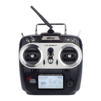
Setting Up Flap->Aileron Mixing
1. Locate the ap->aileron mix-
ing function by scrolling to
the F->A menu with the Up
Down Edit keys. The default
is for it to be inhibited (Inh).
Press the Active/Inhibit
(Clear) key so that the ‘+100%’ display is shown,
meaning the ailerons follow the aps 100%. Depending
on the position of the Ch. 7 switch, either ‘On’ or ‘Off’ will
be ashing.
2. Press the Cursor Right key once, to get to the percent
setting menu. Press the Data +Increase or -Decrease
keys to adjust the amount of mixing to suit.
3. Move the ap knob so the R/D display changes to
L/U, or vice versa, and repeat the setting adjustment for
that side of the travel. You can set an input on each side
of the ap knob.
4. If you want to zero out the amount of mixing on one side
of the knob’s travel, press the Active/Inhibit (Clear) key.
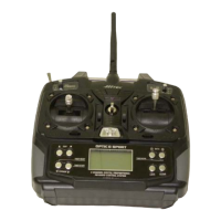
5. If you want to change Set
position, press the Cursor Right
key to change the position of
Flap control channel (VR1)
which value you need, and then
press Clear key.
ADIF - Aileron Differential
Ailerons are used to roll or bank the glider’s wing, but
making a roll or turn has a price. A wing that generates
lift also generates a drag component called induced
drag, meaning that drag is induced as a by-product of the
lifting wing. This means that the wing that is lifting more
is also dragging more, and the resulting drag difference
causes the fuselage of the model to yaw away from the
desired turn direction, exactly the wrong thing to have
happen. This causes even more drag, which can really
hurt a glider’s performance. There are two ways to
reduce the yaw of the fuselage, differential (ADIF) and
rudder coupling (A->R). Both should be used together,
but you only nd ADIF in the glider menus. Aileron
differential causes the ailerons to automatically move
with more UP than DOWN motion, which helps to reduce
induced drag. It helps, along with rudder-coupling, to
make the fuselage point straight into the oncoming air
stream (this is also called
“coordinating the turn”).
The amount of differential is
highly dependent on the
model conguration. A good
starting point is for the down
aileron to move 50% to 75%
as much as the up-moving
aileron.
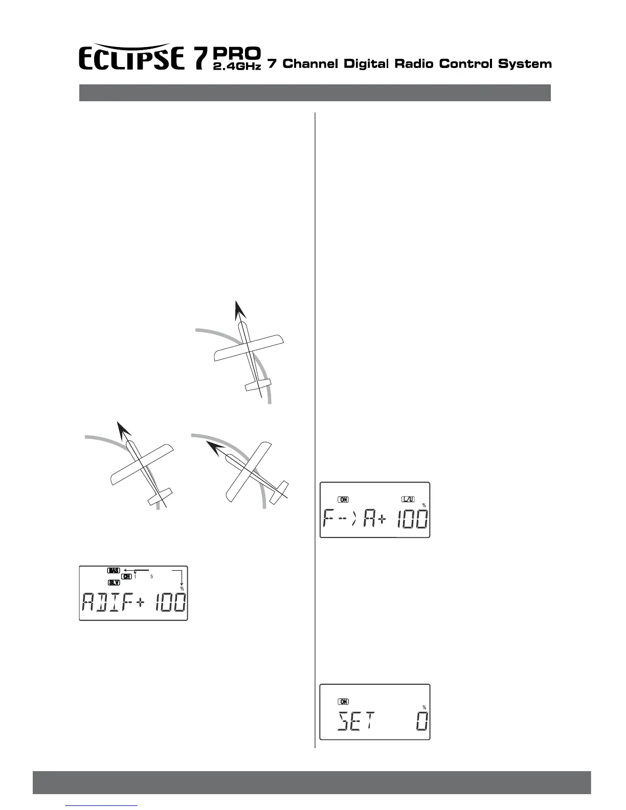
Coordinated turn
fuse lines up with turn direction
(don’t change anything!)
Nose Points inside circle
Toomuch coupling or differential
Reduce one or both.
Nose Point soutside Circle
increase coupling and/or
differential
Setting Up Differential
1. Press one of the Up Down
Edit buttons repeatedly to
select the ADIF window.
To begin with, the function
is already activated, but it’s
set to 100% on both sides
so there is no differential.
2. MAS and the numeral 1 will be ashing together,
showing that CH1 is the affected channel. To set the
differential for the right aileron (CH1) down travel, hold
the aileron stick to the left side (display shows L/U), and
press the Data Decrease key (the right aileron moves
down when left aileron stick is commanded). Continue
reducing the percentage until you reach about 60% to
70%.
3. Make sure that the up travel for the rst aileron (CH1) stays
at 100% by holding the aileron stick to the right side (display
shows R/D) and verifying that the display shows 100%.
Flashing