HQ-004 Quarter-turn Electric Actuator
Installation Operation& Maintenance Manual
Doc No. : HumG-HQ004-21 Rev0 Page 5 / 9 Valve Automation Leader, HKC
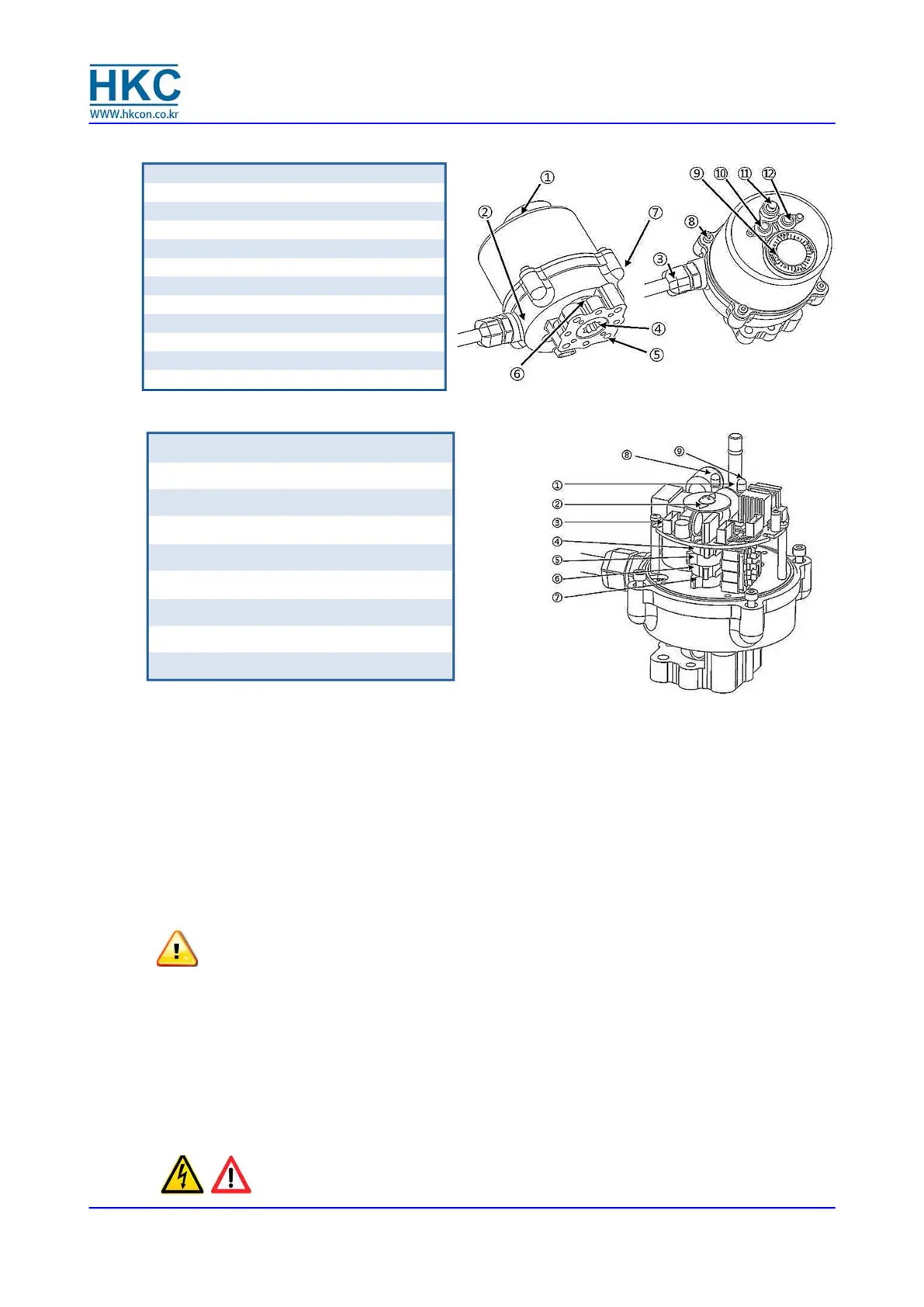
1 Manual push shaft
2 Indicator
3 On/off PCB & Heater
4 Additional close limit switch set
5 Additional open limit switch set
6 Close limit switch set
7 Open limit switch set
8 Fully closed LED lamp (red)
9 Fully open LED lamp (blue)
3.2. External Parts for Standard Models
3.3. Internal parts for standard model
4. Installation
4.1. Pre-installation
4.1.1. Use in general service
Verify the actuator’s nameplate to ensure correct model number, torque output,
operating speed and voltage before installation or use.
It is important to verify that the torque output of the actuator is appropriate for the
torque requirements of the valve and that the duty cycle of the actuator is appropriate
for the intended application.
4.2. Actuator Mounting
Note: Prior to mounting, the actuator must be checked for any damage
Damaged parts must be replaced by original spare parts
4.2.1. Mounting is most easily done with the valve shaft pointing vertically upward. But
mounting is also possible in any other position; the actuator may be mounted in any
position.
4.2.2. The HQ-004 electric actuators are supplied with a female drive output. The ISO5211 bolt
patterns are provided for actuator mounting. High tensile bolts or studs with spring
locking washers must be used.
4.2.3. The valve output shaft must be in lined with the actuator output drive to avoid side-
loading the shaft. To avoid backlash, flexibility in the mounting bracket or mounting
should not be allowed.
CAUTION:
Do not attempt to work on your HKC actuator without first shutting off
the incoming power.
Cable entry (PG 11)x1 & wire(1.2m)
ounting base (F03, F04, F05)
Fully closed LED lamp (red color)
Fully open LED lamp (blue color)
 Loading...