To facilitate ease of conguration of electrical components:
• At least one power harness should be used at a Tee connection, when all 3 panels are powered.
• At least two power harnesses should be used at a Cross connection, when all 4 panels are powered.
• A power harness should be used in a panel positioned at the end of a panel run (See Illustration. 26).
• A power harness should be used in a panel, adjacent to a power pole location, into which a ceiling in-feed is to be
connected.
• Power harnesses should be used in the base rail area and the belt line area of a panel where a jumper cable
connects between the base rail and the belt line - the jumper cable must be routed vertically through an adjacent
panel.
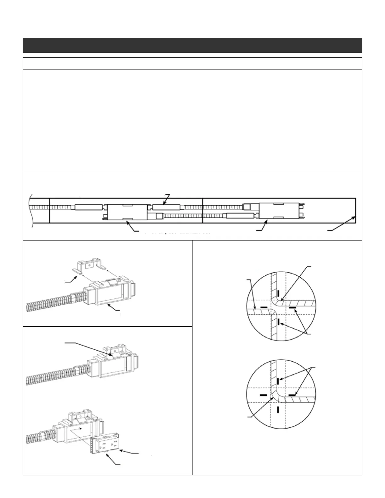
This terminal may be connected or not connected.
If panel at the end of a run is powered,
reverse orientation of harness in last panel.
Power or pass-thru harness
Power harness End of panel run
Inside to inside
of panel
supports.
Outside to
inside of panel
supports.
Panel
supports
Panel
supports
Outside to
outside of panel
supports.
Locking tab
Depress locking tab with a at blade
screw driver and slide power block
outward.
Fully engage receptacle
into power block, then
slide receptacle until it
snaps into a locked
position.
Receptacle
Locking tab
To remove receptacle,
depress locking tab and slide
receptacle to disengage, then
pull receptacle outward.
Engage power block onto
mounting bracket into a
snapped (locked) position.
Power block of power or
pass-through harness
Mounting bracket
(Shown uninstalled)
Pull cable to extend length to:
• Reach to adjacent connection point, and
• Prevent interference with base rail covers at corners.
Illustration 11. 8-Wire Electrical Installation Continued
Illustration 11c. Powering Last Panel, at End of Panel Run:
Illustration 11d. Power/Pass-Thru Harness:
Illustration 11e. Power Block & Receptacle Removal:
Illustration 11f. Routing, at Base rail Panel
Junctions:
Panel System Installation Packet
343-3890A
(03/17)
Page 12 of 27
 Loading...