WARNING
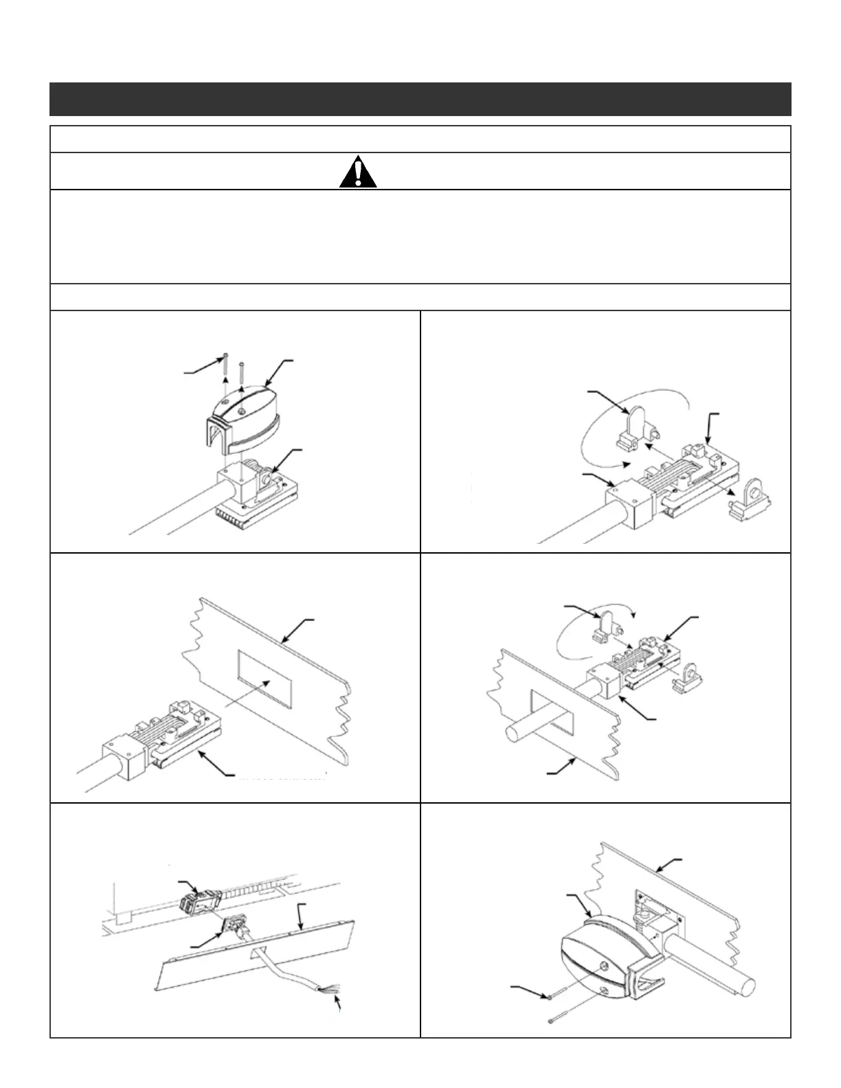
Base rail cover
In-feed connector
Improperly installed electrical components can fail resulting in personal injury and/or property damage.
Connection of the in-feed device to the power source should be performed by a licensed electrician in
compliance with all national and local electrical codes.
To prevent personal injury, ensure in-feed power is disconnected before component installation.
Screw - remove
and save.
In-feed cover -
remove and save.
180° swivel joint
Swivel tab - remove
and save.
In-feed
connector
Swivel joint - disconnect
and hook into in-feed
connector.
In-feed
connector
Swivel tab
Base rail cover
Swivel joint
In-feed cover - install
after power in-feed
and base rail cover is
in place.
Base rail Cover
Screw
Power block
In-feed connector
Base rail cover
Route cable to power source (refer to Electrical Wiring
Diagrams on page 1 for proper wiring connections).
Note: In-feed cable can be shortened. Remove and reapply
UL listing/schematic, near end of cable, as needed.
Illustration 11. 8-Wire Electrical Installation Continued
Base or Ceiling Side In-Feed Installation:
Illustration 11g. Remove In-Feed Cover:
Illustration 11h. Disconnect Swivel Joint and
Remove Swivel tabs:
Illustration 11i. Pass In-Feed Connector Through
Base rail cover:
Illustration 11j. Reassemble Swivel Joint:
Illustration 11k. Connect In-feed Connector:
Illustration 11l. Reattach In-Feed Cover:
Panel System Installation Packet
343-3890A
(03/17)
Page 13 of 27