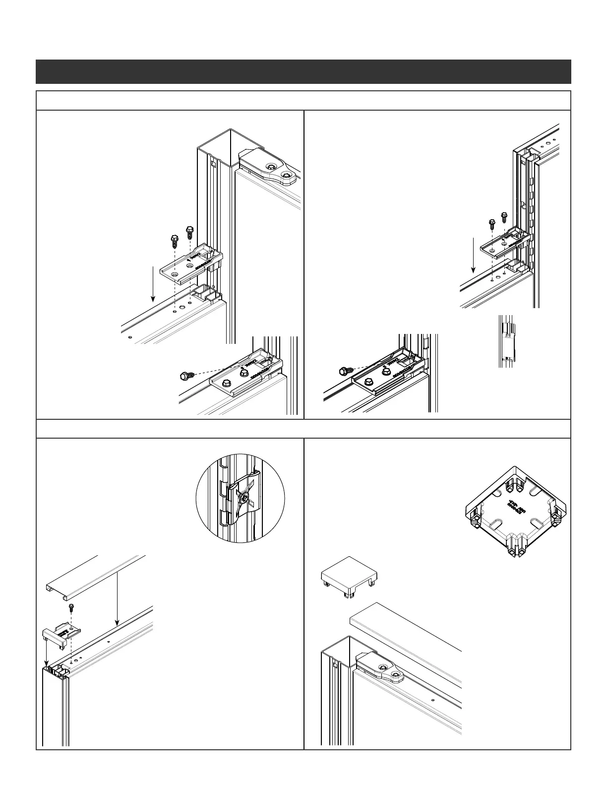
NOTE: Remove pins (Fastener #5)
from stackers on end of run trim
Step 1 - Secure the VH
bracket to the panel
by inserting the tabs
into the vertical tube.
Step 2 - Attach the VH bracket
to the panels using
two screws
provided
(Fastener #1) .
Step 3 - Insert screw provided
(Fastener 1) into the
opening on the VH
bracket and into the
hole on the connector
post.
Step 4 - Insert inline clip.
See Steps 7 thru 9
on page 4.
Step 1 - Secure the VH
bracket to the panel
by inserting the tabs
into the vertical tube.
Step 2 - Attach the VH bracket
to the panels using
two screws
provided
(Fastener #1) .
* To ensure panel is
located properly make
sure the hole in the VH
bracket lines up with
hole on the post.
Step 3 - Insert screw provided
(Fastener 1) into
the opening on the
VH bracket and
into the hole on the
connector post.
Step 1 - Use the curves in
plastic end trim clip to
line up with the curves
in the vertical tube.
Attach with screws
provided
(Fastener #2)
Step 2 - Snap end trim
extrusion over clips.
Step 3 - Engage end of run
transition bracket into
the end trim extrusion.
Step 4 - Attach the top trim
bracket to panel using
screws provided.
(Fastener #1)
Step 5 - The top cap ts
over the attachment
connectors.
Step 1 - Using pliers, break out
the appropriate windows
on the corner connector
top cap.
File rough edges if
necessary.
Step 2 - Press corner
connector top cap
into top of corner
connector post placing
the open windows
over the attachment
connectors.
5a. VH Panel to Corner Connection
Illustration 6. Trim Installations
Illustration 5. Variable Height (VH) Connections
6a. End of Run Trim
5b. VH Panel to Panel Connection
6b. “L”, “T”, “S”, “X” Intersection Trim
Panel System Installation Packet
343-3890A
(03/17)
Page 5 of 27
 Loading...