– 6 –
LOCATION
Before nalizing the location, make sure that consideration has been given for the
electrical conduit, water supply, drain connection, venting (if applicable), tabling (if needed),
chemical feeder replenishment (if applicable) and adequate clearance for opening the door.
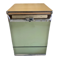
The dishwasher must be level before any connections are made. Turn the threaded feet
(Fig. 1) as required to level the machine and adjust to the desired height.
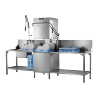
The edge of dish table that overhangs the AM16 wash tank should be turned down and
tted over the top of the dishwasher tank (Fig. 2). Apply an NSF approved sealant between
the overhang of the dish table and the inner wall of the wash tank to prevent leakage (Fig.
2). Fasten the dish tables to the inner wall of the wash tank with non-rusting truss head
screws or rivets (Fig. 2).
For straight-through installations, 30" clearance at the front and 15" clearance at the right
side by 29-1/2" clearance above the nished oor must be provided for service.
For machines equipped with ASR, 30" clearance at the front and 24" clearance at the right
side (or left if ASR is relocated to left side) by 33" clearance above the nished oor must be
provided for service. If ASR is relocated to left side, then 15" clearance is required at right side.
NOTE: For 480-volt units, 20" clearance required at left side.
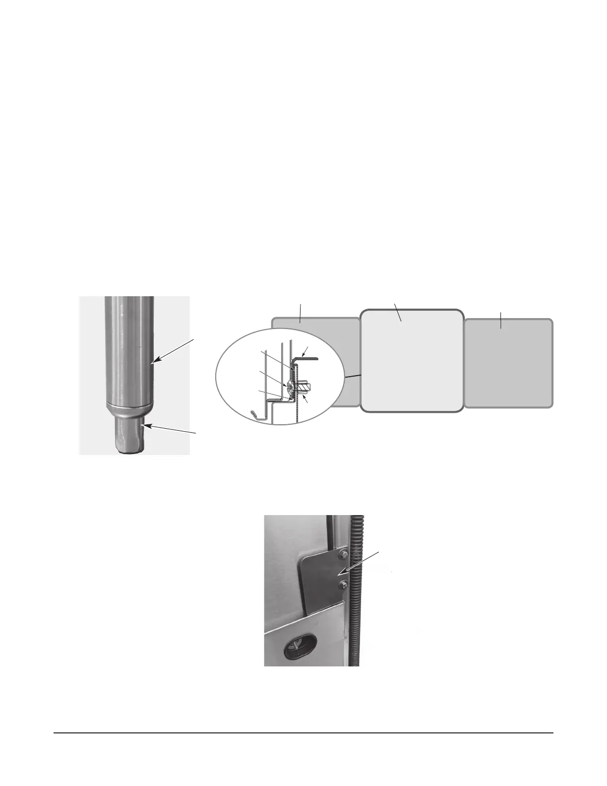
Based on dish table design, rear table brackets (Fig. 3) may need to be adjusted or removed.
Loosen the two bolts and nuts and adjust or remove as required.
NOTE: For AM16-ASR, AM16T-ASR, AM16VL-ADV, AM16VLT-ADV and AM16-SVLT
models, the ASR module may be relocated to the left side of the machine using service kit
part number 00-950446 or sales accessory kit ASRLEFTKIT-AM16.
Fig. 1
Fig. 2
MACHINE
LEG
ADJUSTABLE
FOOT
WASH TANK
DISH TABLE
DISH TABLE
STRAIGHT-THROUGH OPERATION SHOWN
DISH TABLE
NUT
SEALANT
MACHINE SCREW
OR RIVET
INNER WALL OF
WASH TANK
Fig. 3
REAR TABLE
BRACKET
 Loading...