312
-a a
F
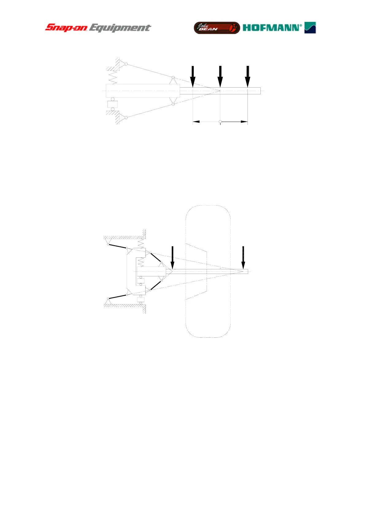
Fig. 8
Force measuring system with one virtual point of support
In Fig. 9 two of the systems illustrated in Fig. 8 are arranged in series at different distances
relative to the node of vibration. Consequently it is possible to establish a force measuring
system for measurement of unbalances in two virtual measuring planes. The two virtual
measuring planes are located in points L and R whereas the relative physical transducers are
marked L’ and R’.
LR
R´
L´
Fig. 9
Two systems arranged in series with different virtual points of support
If for instance a centrifugal force acts on the left-hand node of vibration L, a signal
proportional to the magnitude of the centrifugal force is supplied from transducer L’, whereas
transducer R’ does not supply a signal. On the other hand only transducer R’ will supply a
signal when the centrifugal force acts on the right-hand node of vibration R. This arrangement
is indeed a measuring system as illustrated in Fig. 4 with an outboard rotor and with
correction planes being located between the measuring planes. If forces are applied between
points L and R, the bearing forces are divided in proportion to the relative distances to the
points of support.
Figures 10 to 12 show possible alternatives.
Seite 8 von 99
 Loading...