EasyManua.ls Logo

Hofmann Snap-on Y2k User Manual

Hofmann Snap-on Y2k
99 pages
To Next Page IconTo Next Page
Page #1 background imageLoading...
Page #1 background image
SERVICE
of the Y2k balancing platform
Seite 1 von 99

Table of Contents

Question and Answer IconNeed help?

Do you have a question about the Hofmann Snap-on Y2k and is the answer not in the manual?

Hofmann Snap-on Y2k Specifications

General IconGeneral
BrandHofmann
ModelSnap-on Y2k
CategoryWheel Balancers
LanguageEnglish

Summary

The Vibratory Assemblies

Variants of Vibratory Assemblies

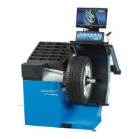
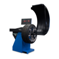
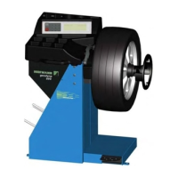
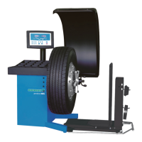
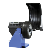
Details the different configurations of the Y2k balancing platform.

Removal and Fitting of the Vibratory Assemblies

Unbalance Transducers and Temperature Sensor

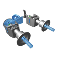
Describes the unbalance transducers and temperature sensor.

Fitting and Pre-stressing Transducers

Step-by-step guide for installing and pre-stressing transducers.

Transducer Continuity and Insulation Checks

Procedures for checking transducer electrical integrity.

The Incremental Encoders

Main Shaft Incremental Encoder

Details the main shaft incremental encoder.

Power-Clamp Incremental Encoder

Describes the incremental encoder for the power-clamp system.

The Drive Systems

Hand Drive System

Explanation of the manual drive system.

Motor Drive System

Explanation of the motorized drive system.

The Brakes

Brakes for Deceleration

Describes brakes used for stopping the main shaft after measurement.

Main Shaft Locks

Explains the mechanisms for locking the main shaft.

The Power-Clamping Device

Functioning of the Power-Clamping Device

Details the operation of the power-clamping system.

Releasing Wheel During Power Failure

Procedure for releasing a wheel during a power outage.

How to Configure the PCM-3350 BIOS

Standard CMOS Setup

Configuration settings for the standard CMOS setup.

BIOS Features Setup

Configuration settings for BIOS features.

Chipset Features Setup

Configuration settings for chipset features.

Power Management Setup

Configuration settings for power management.

Integrated Peripherals

Configuration of integrated peripherals.

Selftest During Startup (CRT/HNA/HWT)

Startup Self-Test Procedures

Checks communication, keyboard, memory, model, and pedal switches.

OPTIMA Hardware and Calibration Tests

Tests OPTIMA hardware, calibration, and specific functions.

General Hardware Tests

Verifies voltage lines, LED current, transducer signals, and auto stop system.

Arm Position and Calibration Checks

Checks SAPE arm positions, calibration status, and service intervals.

Calibration and Service Interval Checks

Checks overall calibration, service intervals, and specific arm calibrations.

Error Codes

H Codes (CRT/HNA/HWT)

Lists and describes kernel error codes starting with 'H'.

E Codes (CRT/HNA/HWT)

Lists and describes error codes starting with 'E'.

K Codes (Kernel Errors)

Structure of an Error Code

Defines the structure and components of kernel error codes.

Module ID Descriptions

Lists and describes module IDs associated with error codes.

Beep Codes

Beeps Definitions

Defines the frequency, duration, and pause for different beep types.

Beep Sequence Indicators

Explains sequences of beeps indicating initialization or errors.

C Codes

Table of C Codes

A comprehensive list of service codes and their functions.

Entering C Codes and Options

CRT Balancer C Code Entry

Instructions for entering C codes on CRT models.

GS Digital Balancer C Code Entry

Instructions for entering C codes on GS models.

HWT Digital Balancer C Code Entry

Instructions for entering C codes on HWT models.

JBEG Digital Balancer C Code Entry

Instructions for entering C codes on JBEG models.

Truck Digital Balancer C Code Entry

Instructions for entering C codes on Truck models.

Saving Settings and System Reset

How to save operational settings, calibration data, and reset the system.

John Bean Functional Description

Definition of Terms

1. Initialisation

Common Initialization Features

General initialization procedures and common features.

Model-Specific Initialization Features

Specific initialization steps for B9000, B9450, and B9460 models.

2. Weight Placement Modes

3. Balancing Results Recalculation

4. Manual Data Entry

5. Weight Bar Operation

6. Sape Operation

High Level Functionality of SAPE Arm

Details the functionality of the SAPE arm for data entry and weight application.

7. Star Menu Access and Operation

8. Wheel Spin Functionality

Common Wheel Spin Features

Explains general wheel spin behavior and error codes.

Model-Specific Wheel Spin Features

Details spin initiation and stopping for different models.

9. Auto-Off Mode

10. Auto-Orientation Mode / Sticky-On-Top

B9460 Specific Auto-Orientation

Specific auto-orientation features for B9460.

11. Split Weight Mode

12. Weight Minimisation

13. Fine Mode Operation

Allows toggling between high and low resolution display of unbalance.

14. User Management (B9450 and B9460 only)

15. User Calibration Procedure

Procedure for calibrating the balancer by the user.

16. Service Menu

17. Service Codes Overview

Lists and explains available service codes.

C0 Setting Factory Defaults

Resets the balancer to factory default settings.

C4 Unbalance Compensation (B9000 Version)

C4 Unbalance Compensation (B9450 / B9460 Version)

C7 Volume of Audible Signals

Adjusts the volume level for audible signals.

C8 Unbalance Threshold Suppression

C11 Setting the Orientation Mode (B9460 only)

Configures the auto-orientation or sticky-on-top mode for B9460.

C12 Counter Indication

C14 User Calibration

C21 Displaying Machine Model and Software Version

C28 Display of the Last 10 Kernel Error Messages

C43 Resetting the Spin Counter C2

C47 Configuring the Non-Volatile Memory

C63 Continuous Measuring Run (b9450 / B9460 only)

C66 Displaying Virtual Dimensions of the Vibratory System

C67 Displaying Vibratory System Phase Shift

C69 Continuous Measuring Runs With Pauses (b9450 / B9460 only)

C72 Measuring the Mechanical Phase Shift of the Vibratory System

C74 Indication of the Position Counter

C75 Indication of all Voltages Supplied to the Analog-to-Digital Converter

C76 Indication of the Drive System Voltages (B9450 / B9460 only)

C80 SAPE Arm Calibration (b9000 / b9450)

C80 SAPE Arm Calibration (b9460)

C81 Flange Position Calibration (b9460)

C82 3D SAPE Arm Calibration (b9460)

C83 Adjustment of the Unbalance Measurement (Factory Calibration)

C84 Compensation of the Residual Main Shaft Unbalance (B9000 version)

C84 Compensation of the Residual Main Shaft Unbalance (B9450 / B9460 version)

C85 Copy Persistent Memory Contents from Controller Board to Opto. Board

C86 Copy Persistent Memory Contents from Opto. Board to Controller Board

C88 Compensation of the Residual Main Shaft Unbalance

C110 Indication of Vcc (5V Line Voltage)

C111 Measure First Harmonic of the Belt (b9450 / b9460)

Factory Configuration Procedure

Summary of User Error Messages

In Field Reprogramming of Balancer

Related product manuals