5. Reconnect the throttle and transmission kickdown linkage and throttle return spring (Holley® P/N 20-89). Operate the carburetor
throttle lever by hand to assure the correct travel (no sticking or binding) by opening to wide open throttle and back to closed
throttle several times. Correct any sticking or binding conditions before proceeding.
NOTE: With the engine turned off, have an assistant slowly press the accelerator pedal to the floor, while you watch the throttle for
any sticking or binding. Correct any sticking or binding conditions before proceeding. Also ensure that you are reaching full
throttle. Many performance problems are traced to partial throttle openings from improperly adjusted linkage. Secondaries will
not open mechanically during this procedure.
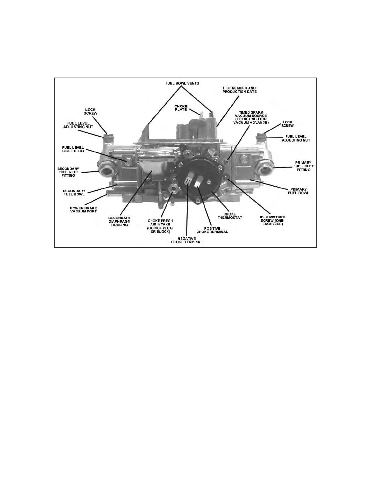
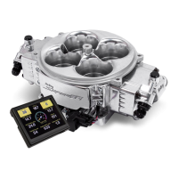
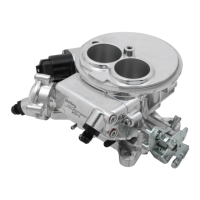
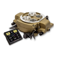
Figure 5 (0-80508S shown)
6. Reconnect the appropriate vacuum hoses to the carburetor, noting the correct fitting from Figure 5 and 6. Replace any cracked or
dry rotted hoses at this time to prevent any vacuum leaks.
A. The full manifold vacuum source in the front of the throttle body provides vacuum for proper operation of the air cleaner, the
pump diverter valve (if equipped), AC/Cruise, and/or the temperature sensing valve. If vacuum for more than one component
is needed, use small plastic vacuum “T”s (available at most automotive stores).
B. The timed spark fitting in the choke side of the primary metering block provides vacuum for the operation of the distributor
vacuum advance. Connect the hose to the distributor, spark delay valve, and/or temperature sensing valve as originally
connected. Again use “T”s as necessary. If any questions arise about the hose connections, consult the proper service
manual.
C. Plug any vacuum source not used.
7. Connect the PCV hose to the PCV fitting in the carburetor.
8. Connect the power brake hose to the fitting as shown in Figure 6.
9. In some cases, the existing fuel line will have to be cut and connected to a “dual feed” fuel line with a length of rubber fuel hose
and a clamp.