This document is a comprehensive installation, tuning, and adjustment manual for Holley® carburetors. It covers several models, including P/N 0-80508S, 0-80508SA, 0-80783C, 0-80459SA (electric choke), and P/N 0-3310S, 0-3310C & 0-3310SA (manual choke). The manual emphasizes the importance of reading and understanding all instructions to ensure proper installation and to preserve the product warranty. Failure to follow the instructions, including the provided pictures, may lead to system failure.
Function Description
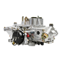
Holley® carburetors are designed as universal replacement carburetors for passenger cars and light truck applications equipped with V-6 and V-8 engines. They are specifically designed for use on "square" flange intake manifolds. The 0-80508S model is a 50-state emission legal replacement carburetor for 1965-69 V-8 applications, with the caveat that in California, those vehicles must have been originally equipped with a four-barrel carburetor. The carburetors are factory wet-flowed and calibrated, meaning their "out of the box" settings should be very close for most adjustments. The manual provides detailed procedures for installation, choke adjustment, idle mixture needle adjustment, float level checks and adjustments, and vacuum-operated secondary tuning.
Important Technical Specifications
The manual provides a carburetor specifications table detailing primary and secondary jetting, pump discharge nozzle size, primary power valve, and secondary diaphragm spring for each listed model.
- Jetting (Main Jets):
- 0-80459SA, 0-80508S, 0-80508SA, 0-3310S, 0-3310C, 0-3310SA: Primary Jet 70, Secondary Metering Plate 21 PLATE* (equivalent to 75 JET).
- 0-80783C: Primary Jet 67, Secondary Jets 73 JETS.
- Carburetors are calibrated at 70° at sea level. Jet size should be decreased by one number for every 2000 ft. increase in altitude.
- Holley® jets are broached, flowed, and stamped according to flow rate; users are warned NEVER to drill jets as this alters flow characteristics.
- It is generally unnecessary to increase jet size more than four numbers greater than the out-of-the-box setting, except possibly with very large volume, plenum-ram manifolds.
- Pump Discharge Nozzle:
- 0-80459SA, 0-80508S, 0-80508SA, 0-3310S, 0-3310C, 0-3310SA: 0.031.
- 0-80783C: 0.028.
- Primary Power Valve: All models listed use a 65 power valve.
- A 65 power valve is operational when manifold vacuum is below 6.5" Hg. This is generally sufficient for most high-performance applications with a manifold vacuum of 12" Hg or higher.
- For engines with manifold vacuum of 12" Hg or less, the power valve size can be determined by dividing the idle manifold vacuum by two.
- Secondary Diaphragm Spring: All models listed use a Black secondary diaphragm spring.
- Recommended Fuel Pressure: 5-7 psi.
- Fast Idle Speed: Factory setting is 1500-1600 RPM.
- Carburetor Hold-Down Nut Torque: 60-80 in./lbs. Overtightening can warp or crack the throttle body.
Usage Features
The manual provides detailed guidance for various aspects of using and maintaining the carburetor:
- Installation:
- Requires careful disconnection and marking of fuel lines, vacuum lines, wiring, PCV hose, choke rod/heat tubes, and throttle/kickdown linkages during removal.
- Installation involves mounting studs, gasket, and the carburetor, followed by progressive tightening of hold-down nuts in a "crisscross" pattern.
- Throttle linkage must be checked for correct travel, ensuring no sticking or binding, which could lead to uncontrolled engine speed.
- Reconnection of vacuum hoses, PCV hose, and power brake hose is detailed, with warnings against vacuum leaks.
- Fuel line installation requires extreme care to prevent foreign particles from entering, and a quality in-line fuel filter (e.g., Holley® P/N 162-523) is mandatory.
- Automatic Transmission Compatibility:
- GM Overdrive Transmissions (TH700R4 or TH200R4): Requires Holley® P/N 20-95 transmission kickdown cable bracket and Holley® P/N 20-40 stud to prevent severe transmission damage. Not designed for ANY other automatic overdrive transmission.
- Chrysler Automatic Overdrive Transmissions: Not designed for use with any Chrysler automatic overdrive transmission; severe transmission damage may result. May require Holley® P/N 20-7 throttle lever extension and Holley® P/N 20-67 stud.
- Ford Automatic Transmissions: Not designed for use with any Ford automatic overdrive transmission; severe transmission damage may result. May require Holley® P/N 20-91 spring and perch kit. Specific instructions for adjusting the transmission kickdown screw are provided.
- Choke Adjustment:
- Electric Choke Models: Choke operation is controlled by rotating the choke cap. Counterclockwise rotation makes the choke come off sooner, clockwise makes it come off later. Factory setting is at "index" or center. Symptoms of too early or too late choke operation (stalling, surging, backfiring, black smoke, poor driveability) are described.
- Manual Choke Models: Connect the choke control cable (Holley® P/N 45-228) to the actuation lever and secure it. Ensure full range of motion.
- Fast Idle Adjustment: For both electric and manual chokes, the fast idle speed screw (located below the choke housing) is adjusted with a 1/4" wrench to increase (clockwise) or decrease (counterclockwise) RPM.
- Idle Mixture Needles:
- These control the air/fuel mixture at idle and are factory preset. Adjustment involves connecting a vacuum gauge to a manifold vacuum port and turning each idle mixture screw (1/8 turn at a time, alternating) to achieve the highest possible vacuum reading (or RPM if using a tachometer). Turning screws in leans the mixture, out richens it.
- Rough idle after adjustment often indicates manifold vacuum leaks, which should be checked and corrected.
- Float Level Check and Adjustment:
- For 0-80508S, 0-80783C, 0-3310C, 0-3310S: Fuel level is observed through a sight plug. It should be even with the bottom edge of the sight plug hole. Adjustment is made by loosening the lock screw on top of the fuel bowl and turning the adjusting nut (clockwise to lower, counterclockwise to raise) in 1/4 rotation increments.
- For 0-80508SA, 0-80459SA, 0-3310SA: Fuel level is observed through a sight glass. It should be at the middle or slightly below the middle of the sight window. Adjustment is similar to other models, but it's noted that revving the engine slightly between adjustments can help evacuate fuel and make adjustment easier.
- Secondary Float Levels: Similar adjustment procedure for secondary bowls, often requiring slight engine revving to draw fuel and allow proper level setting.
- Vacuum Operated Secondary Throttles:
- The manual debunks common misconceptions about secondary operation, explaining that opening secondaries too early can cause a "flat spot" or bogging. Proper calibration ensures a smooth increase in power without a "kick."
- Tuning involves changing the secondary diaphragm spring. Stiffer springs cause secondaries to open later. Users are warned not to clip or trim springs, as this increases spring rate and delays opening. A secondary spring kit (Holley® P/N 20-13) is available.
- Procedure for changing the spring involves removing the choke cap, choke housing, and the three screws retaining the vacuum diaphragm. Care must be taken not to tear the diaphragm or lose the check ball, and to properly align the vacuum passage during reassembly.
Maintenance Features
- Periodic Inspection: Fuel system components, including fuel lines and the carburetor, should be inspected periodically for leakage and hose soundness.
- Hose Replacement: Hoses exhibiting surface cracks (when bent to 180°) should be replaced.
- Tightening Fittings: The presence of liquid fuel necessitates tightening of fittings, hose replacement, and retorquing of fuel system component flange nuts.
- Fuel Bowl Screws: Periodically check the torque on the fuel bowl screws to 25-30 in./lbs. to ensure proper fuel metering.
- Air Cleaner Filter: Air cleaner filter elements should be blown clean with compressed air at 6,000 miles and replaced at 12,000 miles for maximum protection. Upgrading to a Holley® Powershot air filter (Holley® P/N 120-146) is recommended.
- General Optimization: Correct engine timing, spark plug gap and heat range, good working ignition components, and correct operation of the exhaust heat valve are important for optimizing efficiency and performance.
The manual also provides contact information for Holley® Technical Service for parts assistance or information.